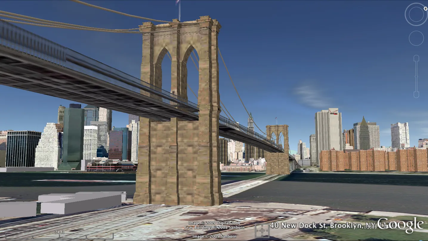
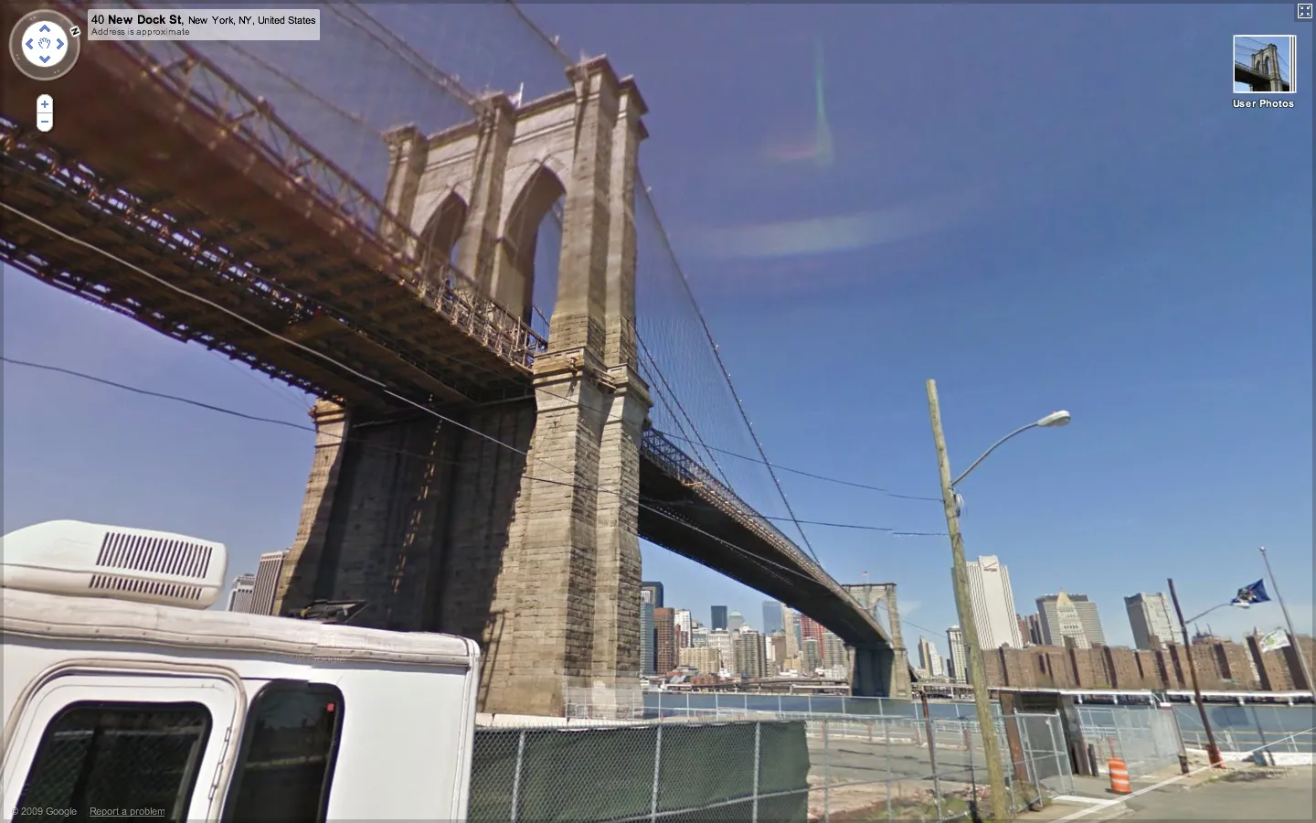
Frontier Nerds: An ITP Blog

Rich 3D Modeling: Scrounging up Data

Google Earth: 3D model of the Brooklyn Bridge from Google Earth

Google Street View: Photo of the Brooklyn Bridge from Google Street View

Grand Theft Auto IV: 3D model of the Brooklyn Bridge from Grand Theft Auto IV

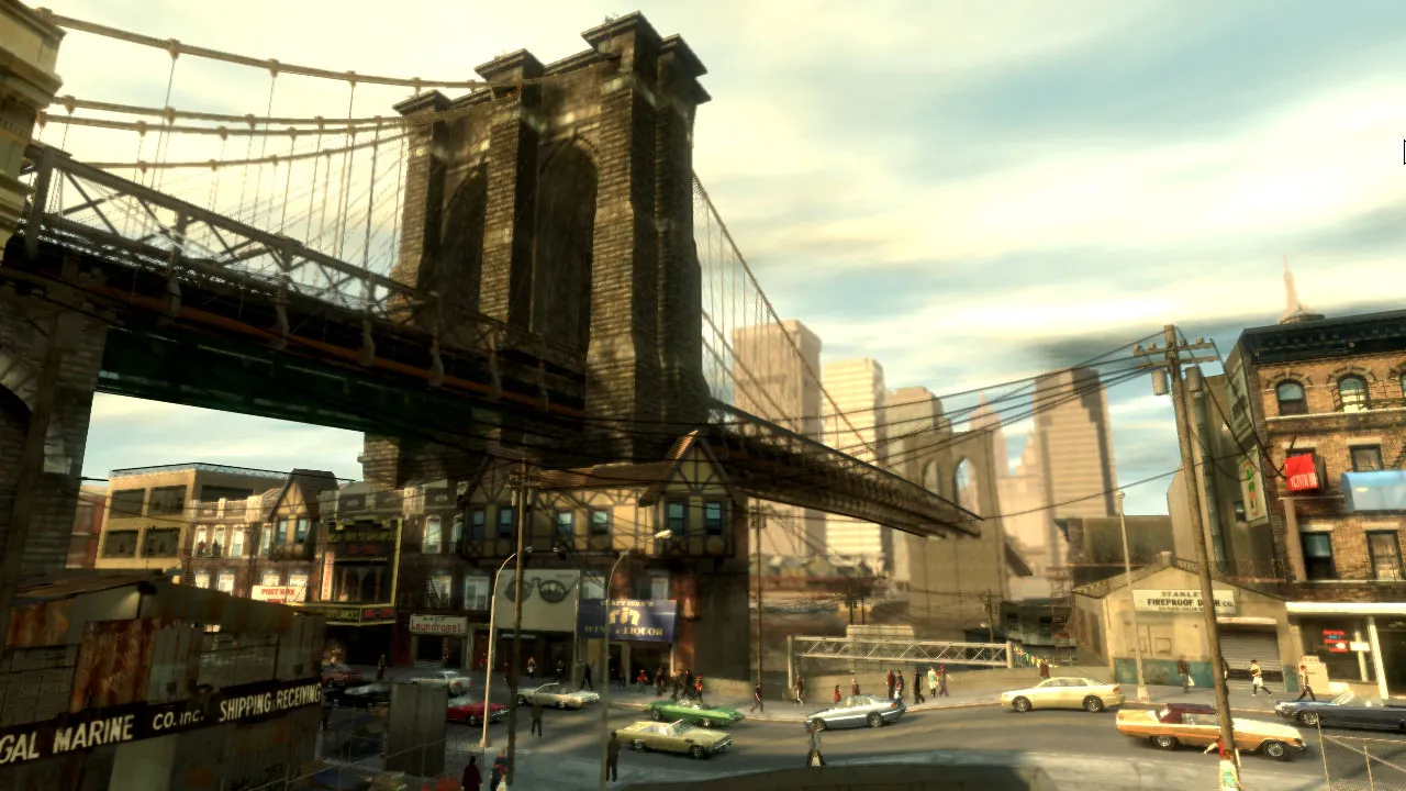
Google Earth’s take on the scene sums up the problems with the state of 3D representations of our environment. Since the Brooklyn Bridge enjoys celebrity status, it gets lovingly hand-modeled either by Google or crowd-sourced obsessives. But the rest of the scene is literally flat. Street View isn’t exactly 3D, but it shows some of the other data Google has on hand that might go into improving the quality of the ground-level experience in Google Earth. The Grand Theft Auto IV screenshot provides some calibration as to how much detail current hardware can render in real time — and although much of the scene is fictional, it highlights the details Google misses, and highlight the fact that the bottleneck to an improved model is data rather than processing power.

So where is this data going to come from? How are we going to fill in the gaps between items that are epic enough to fuss over by hand (like the bridge) and the aerial photography that’s supposed to pass for a backdrop? Where are the cars and the people and the telephone wires that humbly contribute to our sense of place?

I’m not sure the answer to these questions are being pursued very rigorously, but there are a couple of approaches to populating the current, rather sparse 3D representations of the world.

Google’s recently released Building Maker makes it easier to add buildings, but it won’t let you draw a mailbox or a tree.

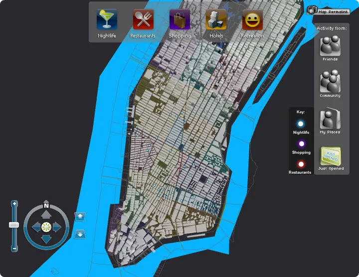
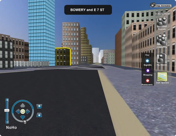
In lieu of crowd-sourcing, a site called UpNext created a (most likely) hand-built 3D approximation of Manhattan, that’s more navigable (but not necessarily more detailed) at street-level than Google Earth’s take on the same space.

Aerial view of a 3D model of Manhattan Ground-level view of a 3D model of Manhattan

A low-budget means of building 3D models can be found in Friedrich Kirschner’s ink scanning project. A cheap camera takes a series of photographs as an object (or person) is submerged into an opaque liquid. The photographic slices are then reconstituted to create a three dimensional point cloud. Not necessarily scalable, but an interesting example of simple and cheap technology doing the work of much more expensive LIDAR or industrial-grade 3D scanning systems.

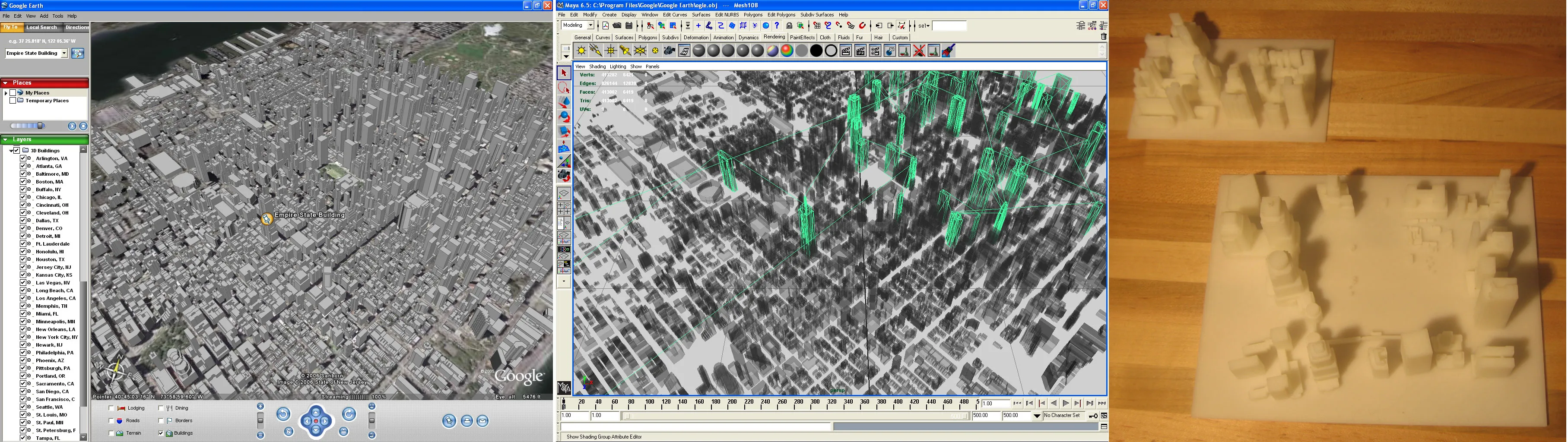
Ogle is a legally unsustainable but nevertheless interesting approach to extracting existing 3D data from closed systems. It basically scrapes OpenGL data after it’s been rendered into standard 3D model formats.

Here it is extracting data from Google Earth for 3D printing:

Three frame process of 3D printing models from Google Earth

A few papers from the 2008 3DPVT conference also show promise in improving the models we have, or building new ones more easily.

Martin Schneider and Reinhard Klein’s paper on improving texturing of height map images by merging several orthographic photographs of the same terrain. Could be of use to Google since they have access to ideal source images. The technique is not necessarily applicable to urban areas, but could improve models of rural areas.

Multiple examples of 3D-rendered terrain

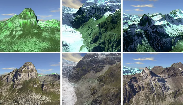
The top row shows a region textured without the technique, the bottom row shows the same region with the improved texturing proposed in the paper.

Geocolor

Clever visualization of Harvard’s campus. Cartographer Andy Woodruff harvested geotagged photographs via Flickr’s API, extracted each frame’s most prominent colors, and then merged and mapped these values to create a top-down average of street-level colors. Bricks make red, parks makes green, etc.

A map of Harvard with a heat-map style overlay representing prominent colors in the are

Full post at Cartogrammar.

Whip vs. Chip

I’ve run into some debate on the floor about which of the two flavors of XBee antenna gives the most range: Whip (left) or chip (right)?

Xbee radio board with a whip-style antenna Xbee radio board with a chip-style antenna

I can’t get a straight answer from the floor, but science delivers thanks to MaxStream’s research on the issue. Turns out the antenna type only makes a difference for long-range outdoor applications:

XBee Antenna Performance

AntennaOutdoor (ft.)Indoor (ft.)
XBeeChip47080
Whip84580
XBee-PROChip1690140
Whip4382140

(Source: Page 3 of Application Note XST-AN019a.)

Photos: Whaleforset, Blankdots

More Media Controller Progress

Slow progress on the shoe music media controller.

Arturo attached the FSRs to the second shoe. Some tweaks were made to the position in hopes of getting better readings. Tom recommended placing the sensors inside the shoe, but for now we’re sticking with the external approach for now since we have it working on the other shoe.

Sensors taped to the bottom of a shoe Foam layered over sensors on the bottom of a shoe

Wear patterns in the shoe informed sensor placement:

Close up of a sensor taped adjacent a worn area on the sole of a shoe

I added a multiplexer to the circuit so that we will be able to get analog readings from all 10 FSRs from a single Arduino.

Also, the wireless serial glitches were fixed by adding cpp delay(10) to the Arduino main loop.

Multiplexing

When the Arduino’s inputs and outputs just aren’t numerous enough, a multiplexer saves the day.

A multiplexer’s basically just a soft switch — you send it a set of digital on / off values to specify which channel you want to read from, and take a look at the “common” pin with an analogRead() on the Arduino, and then rinse and repeat for the next channel (and the next…) until you have all the values you want.

In this way, you can collect readings from a bunch of sensors with the use of just one of the Arduino’s analog pins (plus three or four digital control pins. You can think of the multiplexer as a basic parallel to serial converter — it lets you take a bunch of different signals and put them into a single stream of data.

In short, it’s an easy way to add inputs and outputs to your Arduino.

It’s also possible to string several together to get control of even more inputs and outputs. More about this, including schematics, is available on the Arduino website.

Multiplexers come in a variety of flavors… 8 channel varieties (like the 4051) use a 3-bit digital channel picker, while 16 channel models like the 4067 shown below use a 4-bit channel picker. Everything you need to know about the pins and channel encoding is available in the data sheet.

The circuit I’m using for the media controller project looks like this. All of the sensors aren’t hooked up, but it gives the idea.

Multiplexer circuit overview

Note The resistor between the common pin and ground is critical — I was getting noisy readings at first; the resistor fixed it:

Multiplexer circuit detail

Here’s some Arduino code to read each channel from a multiplexer and then send each value out over serial in a comma-delimited format:

// 4067 16 Channel Multiplexer

// Based on the code for the 8 channel 4051 available here:
// https://playground.arduino.cc/Learning/4051/

// Here's a handy datasheet for the 4067:
// https://www.sparkfun.com/datasheets/IC/CD74HC4067.pdf

// How many of the 16 channels do we want to actually read?
// set this to a lower number to read a fraction of the channels
int activeChannels = 16;

// Keep count of which channel we're reading.
int channel = 0;

// Set the common input / output pin.
int pinCommon = 0;

// Set which pins tell the multiplexer which input to read from.
int pinS0 = 2;
int pinS1 = 3;
int pinS2 = 4;
int pinS3 = 5;

void setup() {
  // Set the switch pins to output.
  pinMode(pinS0, OUTPUT);
  pinMode(pinS1, OUTPUT);
  pinMode(pinS2, OUTPUT);
  pinMode(pinS3, OUTPUT);

  // Fire up the serial.
  Serial.begin(9600);
}

void loop () {

  // Loop through the channels and read each one.
  for (channel = 0; channel < activeChannels; channel++) {

    // Get the switch states from the channel number, and
    // send the state to the multiplexer to read from that
    // channel. This configuration covers all the channels,
    // but doesn't read them in a sequence that matches the datasheet.
    // (This works, but needs revision.)
    digitalWrite(pinS0, (channel & 15) >> 3);  // bit 4
    digitalWrite(pinS1, (channel & 7) >> 2);   // bit 3
    digitalWrite(pinS2, (channel & 3) >> 1);   // bit 2
    digitalWrite(pinS3, (channel & 1));        // bit 1

    // Read the common pin and send it out over serial.
    Serial.print(analogRead(pinCommon), DEC);

    if(channel < (activeChannels - 1)) {
      // Separate each channel with a comma.
      Serial.print(",");
    }
    else {
      // If it's the last channel, skip the
      // period and send a line feed instead.
      Serial.println();
    }

  }

  // Take a breath.
  delay(10);
}