Frontier Nerds: An ITP Blog

Egg Dissolve

Eric Mika

The mechanisms class was charged with creating egg-cracking Rube Goldberg machines for the first week’s assignment. Rather than breaking the egg shell through brute force, we tossed around the idea of dissolving the egg shell entirely.

Luckily there was some muriatic acid lying around the shop, so we ran a quick experiment. The shell dissolves, but it takes about 20 minutes, and what’s left isn’t a broken egg, but a layer of internal membrane which keeps the de-shelled egg intact. Interesting, but not well suited to the purposes of our machine-to-be, so we shelved the idea.

(Maybe it was too clever by half to begin with.)

(Science music by Boards of Canada.)

Triangle Soup

Eric Mika

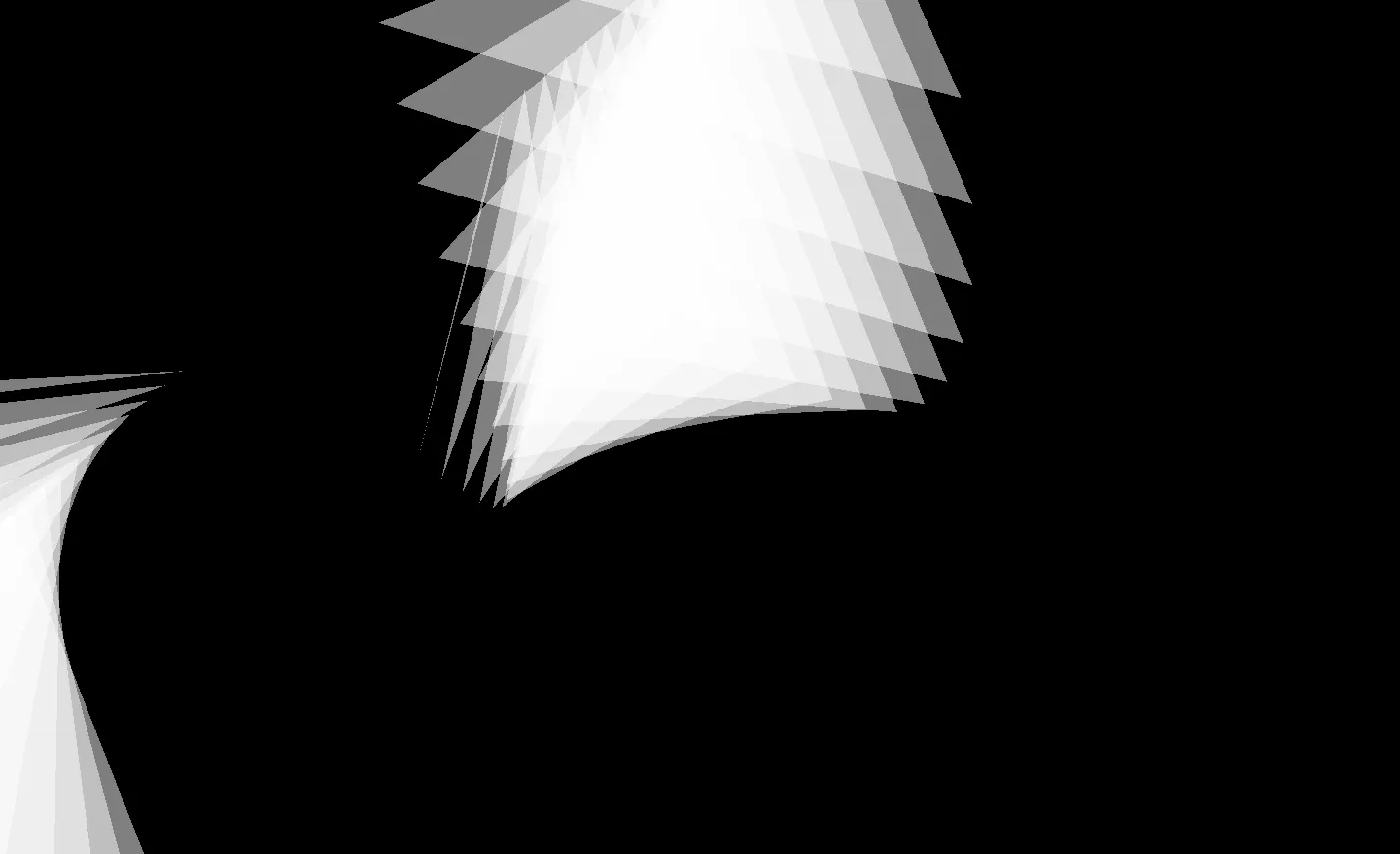
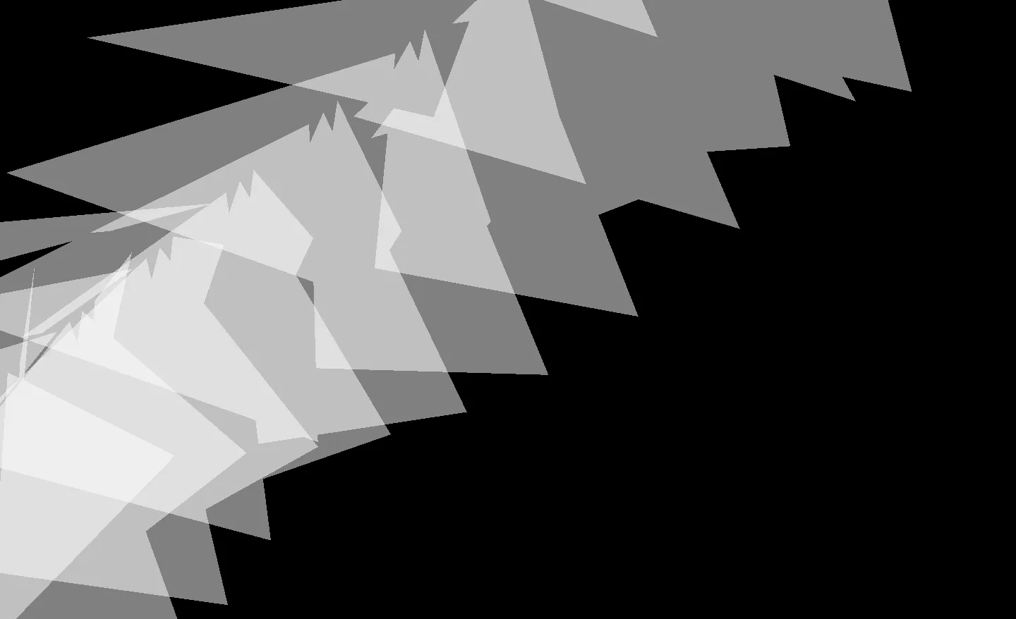
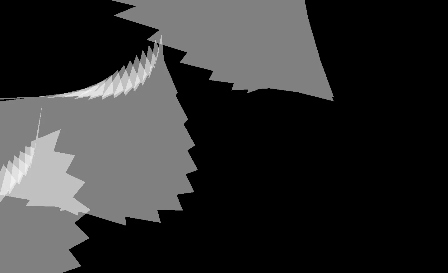
A quick assignment for GLART, drawing an animated field of triangles.

White triangles on a black backgroundMore white triangles on a black backgroundEven more white triangles on a black backgroundYet more white triangles on a black background

Here’s the code:

package mika;
import java.awt.event.MouseEvent;
import javax.media.opengl.*;
import jocode.*;

/**
* DemoBasicGeometry.java
*
* Demonstrate six types of geometry using glBegin()...glEnd()
*
* napier at potatoland dot org
*/


public class Week1 extends JOApp {

// Set the mouse position in a way that's
// useful for translating objects at 0 Z
public float screenCursorX;
public float screenCursorY;
public float tempValue;
public float sizeMult;

/**
* Start the application, Run() initializes the OpenGL context, calls setup(),
* handles mouse and keyboard input, and calls draw() in a loop.
*/

public static void main(String args[]) {
// create the app
Week1 demo = new Week1();

// set title, window size
windowTitle = "Hello World";
displayWidth = 1440;
displayHeight = 900;

// start running: will call init(), setup(), draw(), mouse functions
demo.run();
}

/**
* Initialize settings. Will be called once when app starts. Called by
* JOApp.init().
*/

@Override
public void setup() {
// set a background color
gl.glClearColor(0 f, 0 f, 0 f, 1 f);

// Move over to my second monitor for testing...
// TODO Disable this IRL
frame.setLocation(-1440, 150);
}

/**
* Render one frame. Called by the JOApp.display() callback function.
*/

@Override
public void draw() {

// Clear screen and depth buffer
gl.glClear(GL.GL_COLOR_BUFFER_BIT | GL.GL_DEPTH_BUFFER_BIT);

// Select The Modelview Matrix (controls model orientation)
gl.glMatrixMode(GL.GL_MODELVIEW);

gl.glEnable(GL.GL_BLEND);
gl.glBlendFunc(GL.GL_SRC0_ALPHA, GL.GL_ONE_MINUS_SRC_ALPHA);
// gl.glBlendFunc(GL.GL_ONE, GL.GL_ONE);

// Reset the Modelview matrix
// this resets the coordinate system to center of screen
gl.glLoadIdentity();

// Where is the 'eye'
glu.gluLookAt(0 f, 0 f, 10 f, // eye position
6 f, 1 f, 0 f, // target to look at
0 f, 1 f, 0 f); // which way is up

// color will affect all the following verts
gl.glColor4f(1 f, 1 f, 1 f, 0.5 f);
// gl.glColor3f(1f, 1f, 1f);

sizeMult = 3;
tempValue = (tempValue + .02 f) % 1000;

for (int i = 0; i < 200; i++) {
gl.glRotatef(tempValue, tempValue, tempValue, tempValue);

gl.glTranslatef(.1 f, .1 f, .1 f);

gl.glBegin(GL.GL_TRIANGLES); {
// top
gl.glVertex3f(0 f, 0 f, 0 f);

// lower left
gl.glVertex3f(-0.5 f * sizeMult, -1 f * sizeMult, 0 f);

// lower right
gl.glVertex3f(0.5 f * sizeMult, -1 f * sizeMult, 0 f);
}
gl.glEnd();
}

// reset vertex color to white
gl.glColor3f(1 f, 1 f, 1 f);
}

@Override
public void mouseMoved(MouseEvent _event) {
// Call the parent method since it actually gives us the
// Better just to copy the whole method?
super.mouseMoved(_event);
screenCursorX = cursorX / (displayWidth / 10 f);
screenCursorY = cursorY / (displayHeight / 10 f) - 3 f;
}

}

Window Drop

Eric Mika

I spent an unreasonable portion of my childhood in the back seat of a car, staring out the window. Rainy days, in particular, allowed for one of the more confounding means of passing the time: attempting to predict and understand the movements of water drops on the window.

Simulation of rain streaming down a window

Interactive Versions

References

Video: Susan Prentiss

Real-time Sky Hiatus

Eric Mika

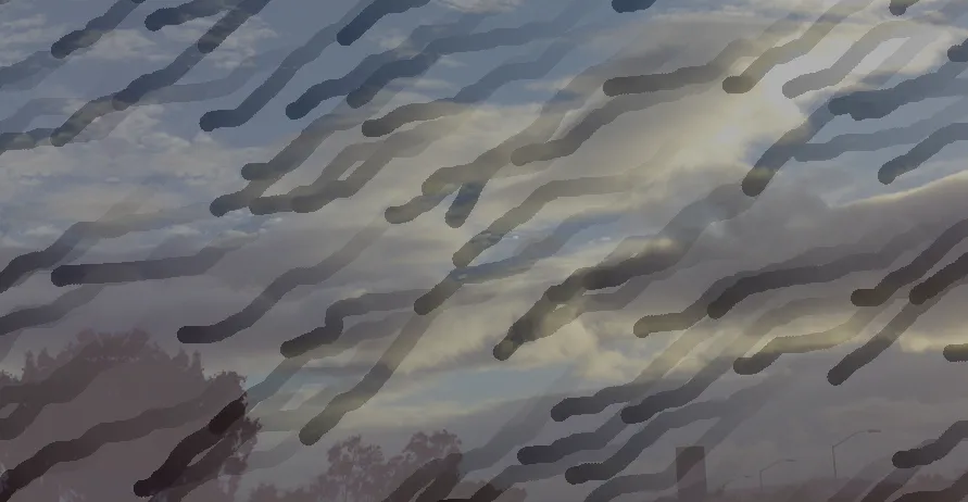
The output from my real-time sky cam remains inconsistent. The color of the sky was supposed to set the background color of this blog… but I’m having second thoughts.

I was expecting shades of blue, but ended up with yellows and browns… assaults on the eyes that are too much to bear. Until I can muster a better color-sensing solution, I’m returning the blog background to its original light-gray. In the mean time, the sky camera will continue to send its uninspired color values up to Pachube every minute.

And so, failure: The whole idea was to lighten up and relinquish some aesthetic control to an unknowing third party. It was more than I could handle. For shame.

Buzz Pot: A Variable Detent Potentiometer

Eric Mika

In the course of developing Brain Radio with Arturo and Sofy, we saw the need for a means of tuning between an arbitrary, and potentially unstable number of channels. For the sake of context, Brain Radio is a head-mounted EEG-based broadcast system — everyone with a headset can tune into anyone else with a headset, and listen to sounds synthesized by that person’s brain waves.

How, exactly, would the tuning process take place? We knew a few things:

  • We wanted to use a dial to leverage associations with radio / tuning / broadcast / analog.
  • We would need some kind of tactile feedback, since the dial would be mounted on the headset, outside of the wearer’s field of view.
  • The number of available stations / channels would vary — if three people were in range, the dial would need to be able to tune to three positions. If more channels came online or dropped out, the interface would have to adapt.

What we really wanted was a potentiometer with detents, to make it easy to click-click-click from station to station. Detents also summon a tactile delight rivaled only by toggle switches and large mechanical levers. They inflate the sense of intention associated with an action: They make you feel like you know what you’re doing.

The catch, of course, is that potentiometers with detents have a finite number of them, and they’re set at the factory. If we bought five-detent pots and ended up with six radio channels to tune between, we were SOL. What we needed was a variable detent potentiometer.

Google turned up some shady, product-less patent filings. And the PComp list confirmed that no such device existed — and then suggested something very savvy: use something else to generate the tactile feedback.

How about a vibration motor…

So I did exactly that. A vibration motor, some hot glue, a potentiometer, and some code all collided to create the buzz pot:

The video doesn’t really communicate the physical feedback coming through the pot when channel thresholds are crossed, but in practice it works pretty well. The number of channels is easily changed in software — and the resistance range of the potentiometer is simply divided up so a given range of values represent a single channel.

For example, a three channel setting would put channel 1 between analog values 0 and 341, channel 2 between 341 and 682, and then channel 3 between 682 and 1023. When the pot passes from one channel range to the next, the microcontroller flips on the transistor controlling power to the vibration motor for a fraction of a second, sending a mechanical buzz through the pot that lets the user feel when they’ve changed channels, even if they can’t see what they’re doing.

Development was relatively simple. Hot glue held up surprisingly well to the vibration motor.

Buzz pot motor mountedBuzz pot bottom view

The basic test configuration includes a seven-segment LED display so I could verify when the channels changed.

Buzz pot test configurationBuzz pot clamped to a table for testing

Here’s the schematic. The seven-segment display adds some complexity… it’s really just for troubleshooting purposes (sending the channel status out over serial would be much simpler). Even then, a shift-register would allow for more sensible use of the Arduino’s pins if this were more than a proof of concept. The TIP 120 between the Arduino and the vibration motor is definitely overkill, I just put it in place since Brain Radio was going to have discrete power sources and it would have made sense to put the motor on the non-Arduino power supply. (Some of the graphics in the schematic were adapted from the Fritzing project.)

Buzz Pot Schematic

And finally, the code:

// Buzz Pot
// Eric Mika, 2009
// Provides tactile feedback for a potentiometer to denote changes
// from one value range to another. Ideal for situations where an unknown
// number of values must be set by a single potentiometer.
// To do:
// 1. Debounce the thresholds.
// 2. Handle fringe-case runtime channel count changes.

int vibrationPin = 9; // Turns the vibration motor on and off through a transistor.
int potPin = 0; // Reads the potentiometer.
int potValue = 0; // Stores the potentiometer value.

int channels = 10; // Number of values selectable by the pot.
int currentChannel = 0; // Starting value.
int lastChannel = 0;

int vibDuration = 200; // How long to turn the motor on when thresholds are crossed.
unsigned long vibStart = 0; // Keep track of time so we know when to turn off the motor.

// Map digital pins to their respective LEDs in the 7 segment display.
// Could use a shift register instead to save pins.
int dispA = 2;
int dispB = 3;
int dispC = 4;
int dispD = 5;
int dispE = 6;
int dispF = 7;
int dispG = 8;

void setup() {
// Set up 7 segment display pins.
pinMode(dispA, OUTPUT);
pinMode(dispB, OUTPUT);
pinMode(dispC, OUTPUT);
pinMode(dispD, OUTPUT);
pinMode(dispE, OUTPUT);
pinMode(dispF, OUTPUT);
pinMode(dispG, OUTPUT);

// Set up vibration pin.
pinMode(vibrationPin, OUTPUT);
}

void loop() {
// Read the analog input into a variable, correct for value inversion.
potValue = 1023 - analogRead(potPin);

// If 10 channels, return a number between 0 and 9...
// Constrain to catch rounding errors at the top end.
currentChannel = constrain(potValue / (1023 / channels), 0, channels - 1);

// Show the current channel number on the 7 segment display.
displayDigit(currentChannel);

// Vibrate if we change channels.
if (lastChannel != currentChannel) {
vibStart = millis();
}

// Keep vibrating for the full duration...
if ((millis() - vibStart) <= vibDuration) {
digitalWrite(vibrationPin, HIGH);
}
else {
digitalWrite(vibrationPin, LOW);
}

lastChannel = currentChannel;
}

// Shows a number on the 7 segment display.
// It's a common anode model, so LOW is actually on.
void displayDigit(int digit) {
switch (digit) {
case 0:
digitalWrite(dispA, LOW);
digitalWrite(dispB, LOW);
digitalWrite(dispC, LOW);
digitalWrite(dispD, LOW);
digitalWrite(dispE, LOW);
digitalWrite(dispF, LOW);
digitalWrite(dispG, HIGH);
break;
case 1:
digitalWrite(dispA, HIGH);
digitalWrite(dispB, LOW);
digitalWrite(dispC, LOW);
digitalWrite(dispD, HIGH);
digitalWrite(dispE, HIGH);
digitalWrite(dispF, HIGH);
digitalWrite(dispG, HIGH);
break;
case 2:
digitalWrite(dispA, LOW);
digitalWrite(dispB, LOW);
digitalWrite(dispC, HIGH);
digitalWrite(dispD, LOW);
digitalWrite(dispE, LOW);
digitalWrite(dispF, HIGH);
digitalWrite(dispG, LOW);
break;
case 3:
digitalWrite(dispA, LOW);
digitalWrite(dispB, LOW);
digitalWrite(dispC, LOW);
digitalWrite(dispD, LOW);
digitalWrite(dispE, HIGH);
digitalWrite(dispF, HIGH);
digitalWrite(dispG, LOW);
break;
case 4:
digitalWrite(dispA, HIGH);
digitalWrite(dispB, LOW);
digitalWrite(dispC, LOW);
digitalWrite(dispD, HIGH);
digitalWrite(dispE, HIGH);
digitalWrite(dispF, LOW);
digitalWrite(dispG, LOW);
break;
case 5:
digitalWrite(dispA, LOW);
digitalWrite(dispB, HIGH);
digitalWrite(dispC, LOW);
digitalWrite(dispD, LOW);
digitalWrite(dispE, HIGH);
digitalWrite(dispF, LOW);
digitalWrite(dispG, LOW);
break;
case 6:
digitalWrite(dispA, LOW);
digitalWrite(dispB, HIGH);
digitalWrite(dispC, LOW);
digitalWrite(dispD, LOW);
digitalWrite(dispE, LOW);
digitalWrite(dispF, LOW);
digitalWrite(dispG, LOW);
break;
case 7:
digitalWrite(dispA, LOW);
digitalWrite(dispB, LOW);
digitalWrite(dispC, LOW);
digitalWrite(dispD, HIGH);
digitalWrite(dispE, HIGH);
digitalWrite(dispF, HIGH);
digitalWrite(dispG, HIGH);
break;
case 8:
digitalWrite(dispA, LOW);
digitalWrite(dispB, LOW);
digitalWrite(dispC, LOW);
digitalWrite(dispD, LOW);
digitalWrite(dispE, LOW);
digitalWrite(dispF, LOW);
digitalWrite(dispG, LOW);
break;
case 9:
digitalWrite(dispA, LOW);
digitalWrite(dispB, LOW);
digitalWrite(dispC, LOW);
digitalWrite(dispD, LOW);
digitalWrite(dispE, HIGH);
digitalWrite(dispF, LOW);
digitalWrite(dispG, LOW);
break;
default:
digitalWrite(dispA, HIGH);
digitalWrite(dispB, HIGH);
digitalWrite(dispC, HIGH);
digitalWrite(dispD, HIGH);
digitalWrite(dispE, HIGH);
digitalWrite(dispF, HIGH);
digitalWrite(dispG, HIGH);
}
}