Arturo, Yin, and myself are all hoping we can cut the wires between an Arduino and a laptop for our upcoming media controller project. We might even have a legitimate reason to bother: our controller is wearable, and the wearer should be able to dance / spin / walk and generally move freely.
So I picked up a couple of XBees in hopes of figuring out which end is up.
After about three hours of fiddling, we got the wireless working — sending serial from the Arduino to my laptop. Our system only needs to send data one way from the microcontroller to a PC, so we didn’t worry about / fuss with sending data the other way. (Though I’d guess it’s as simple as sending serial out from Processing, probably with the ID of the XBee or something similar.)
Here’s what we did and where we ran into trouble:
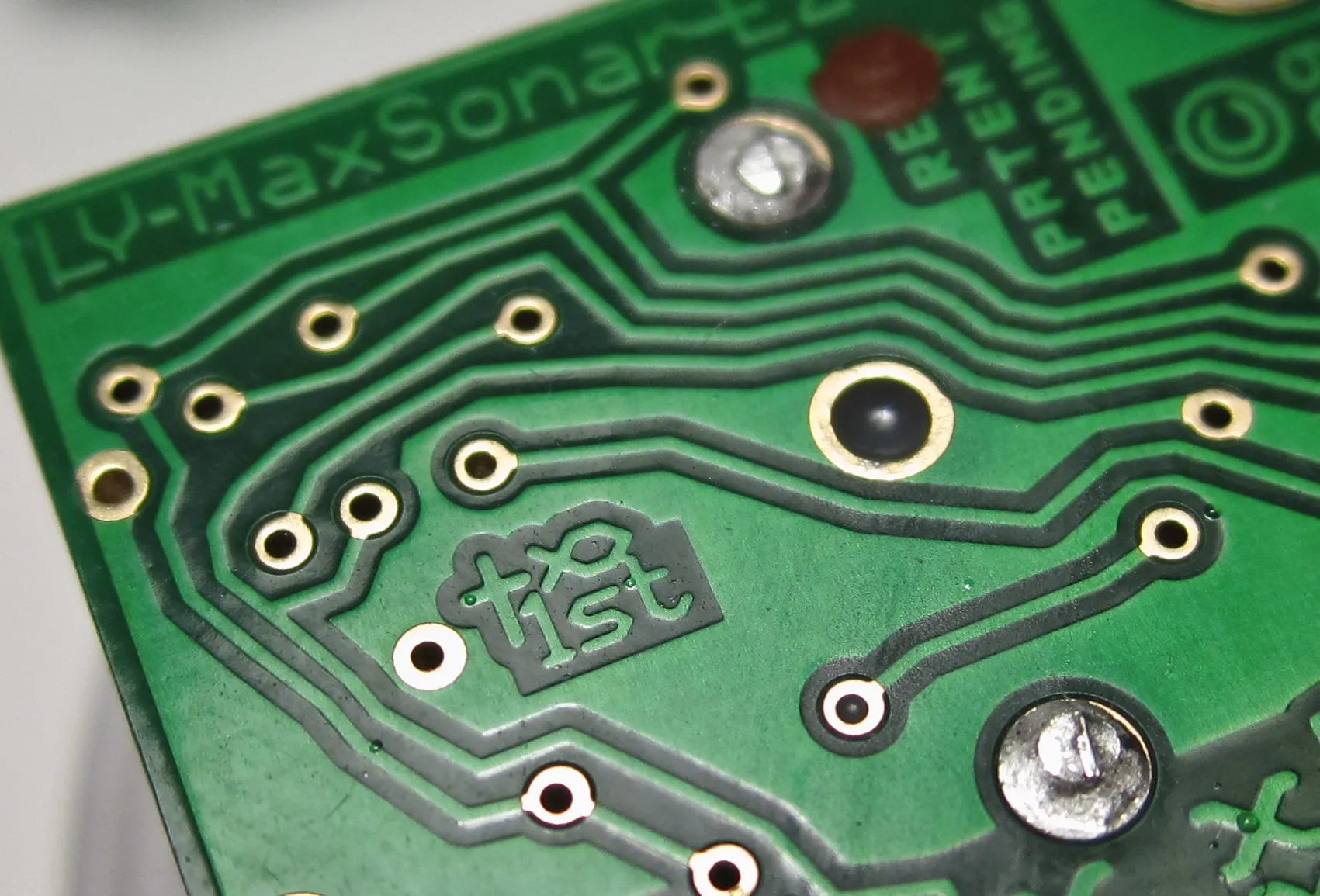
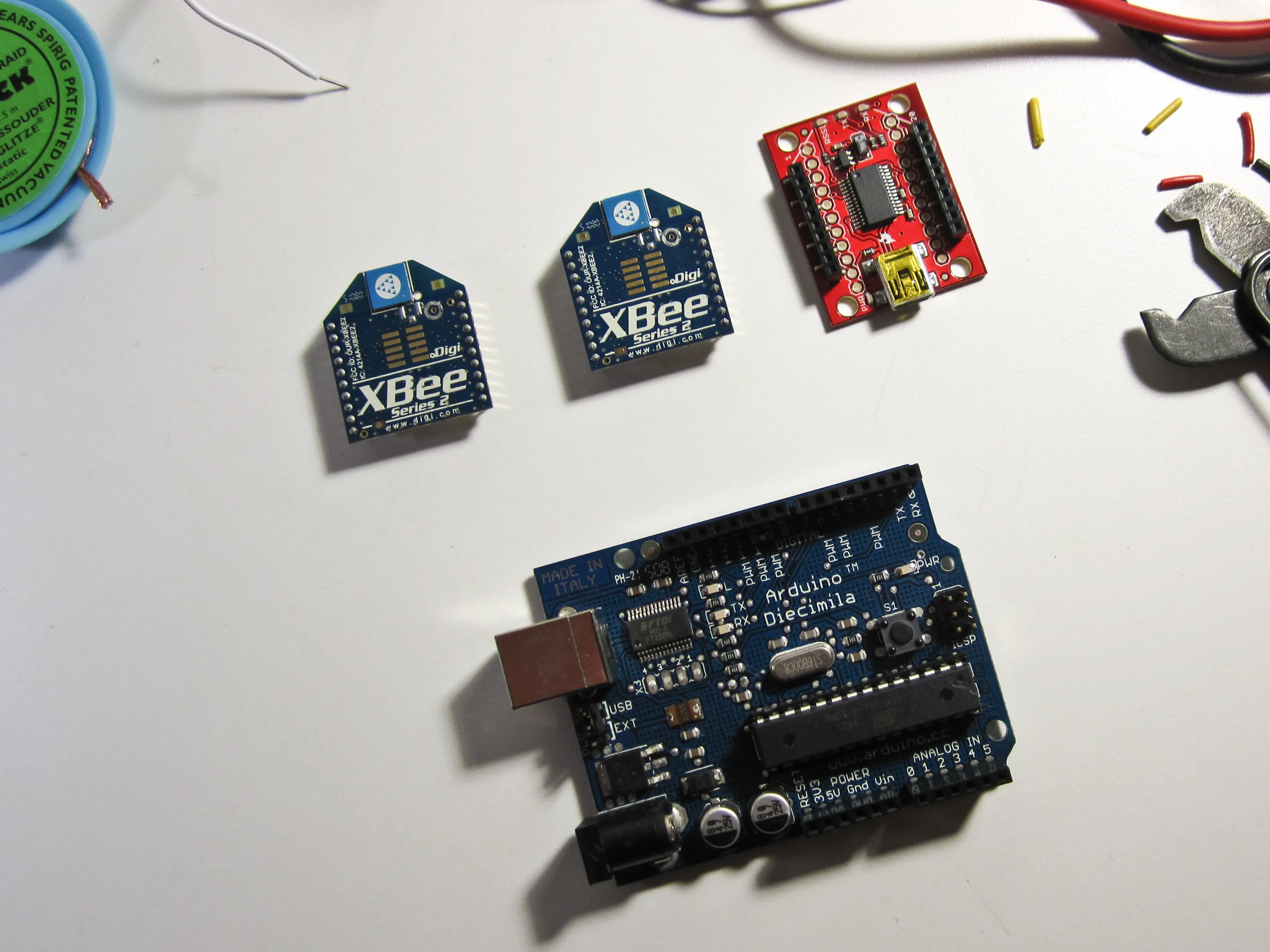
- First we amassed the parts… an Arduino, two XBee modules, a shield to bring the XBee’s tight pin spacing into alignment with a standard breadboard (not pictured), and a small board that’s supposed to take the XBee from serial to USB via an FTDI chip. This is kind of cheating (I’d learn more by wiring this circuit myself) … but it’s very handy.
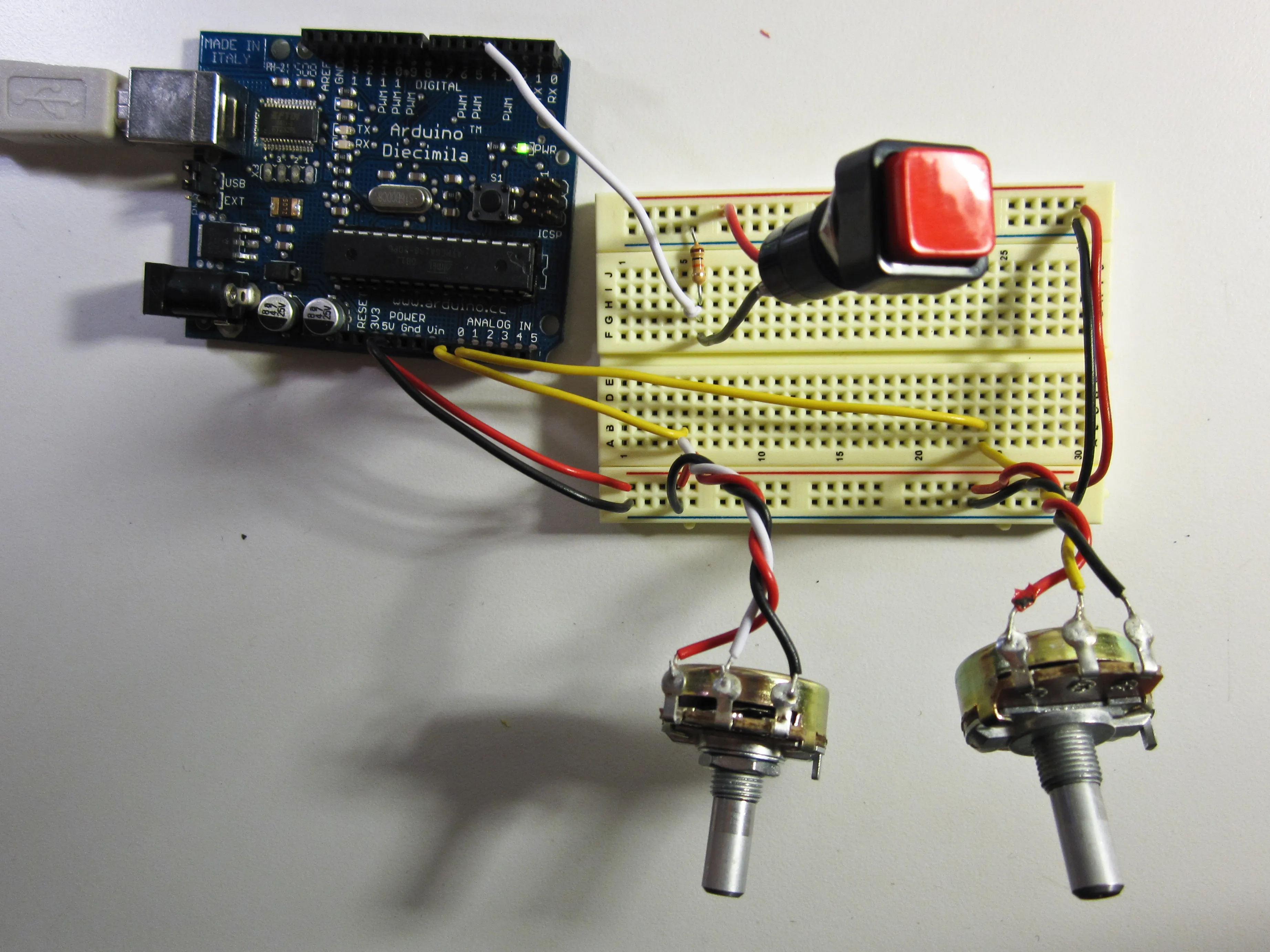
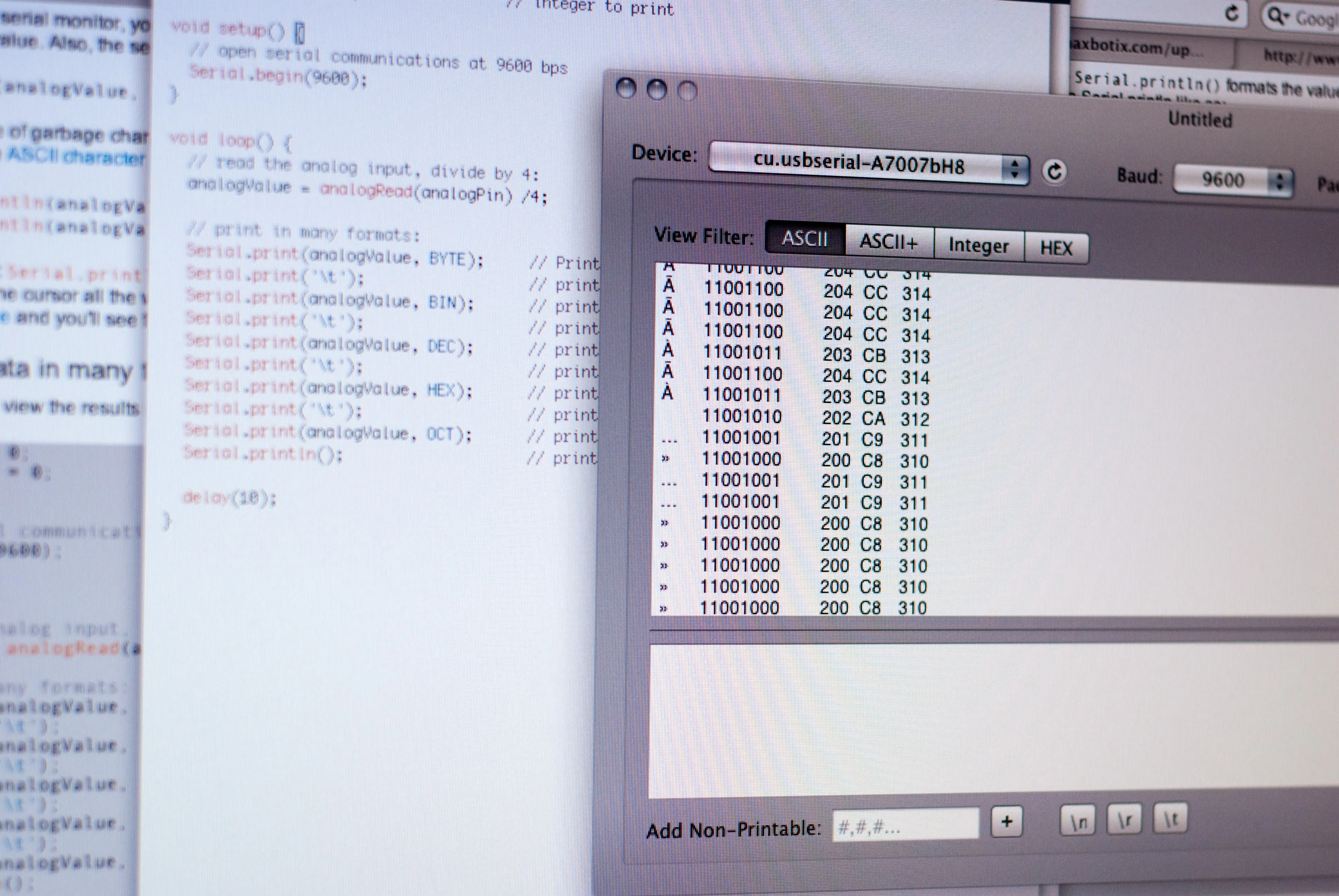
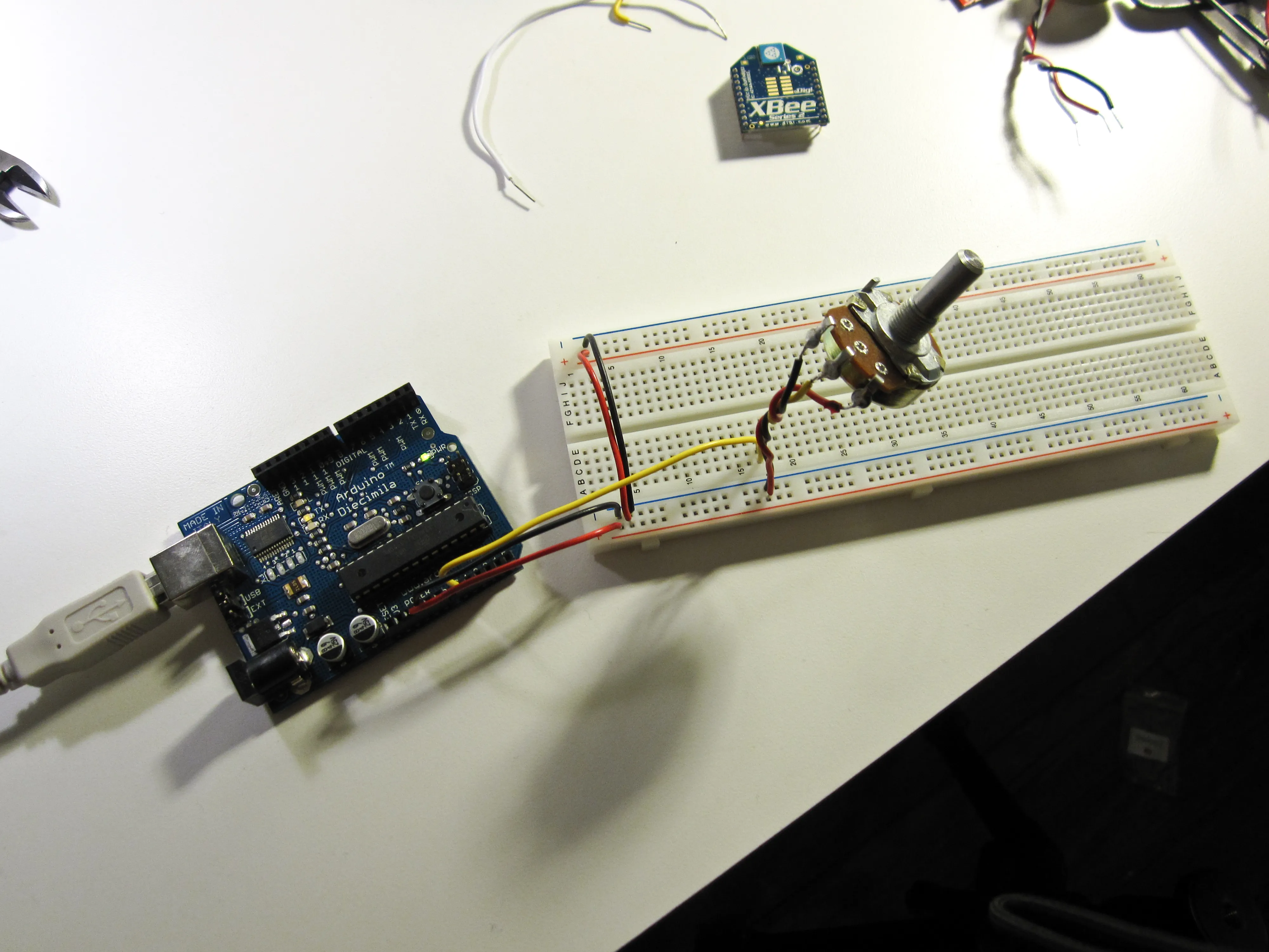
- We assembled a wired version of the circuit I want to make wireless. It’s the most basic thing imaginable: The AnalogInSerial example from the Arduino IDE. I made sure this was sending out serial like it should before moving on to the next step.
-
Next I wired the XBee onto the breadboard. (Note that the XBee’s pins are spaced more tightly (2mm / pin) than the 0.1” inch spacing on a standard breadboard. To drop an XBee onto a breadboard, you’ll need a small shield to compensate for this difference. (I used a $10 shield from the NYU computer store, but you can assemble one for a few bucks less by picking up two 10 pin sockets, an XBee breakout board, and a strip of break-away headers from Sparkfun.
Note that the XBee wants 3.3 volts of power. I’m not sure if the 5 volts we normally work with on Arduino is enough to fry a $30 XBee module, but I didn’t want to find out. My Arduino already has a 3.3 volt source, so I just used that, but if it’s not available on your Arduino you can wire one up easily enough using a voltage regulator.
-
Getting the XBees to communicate required some firmware voodoo. Note: This only applies if you have a Series 2 XBee! I made the mistake of buying an XBee Series 2 instead of the simpler Series 1. In certain cases, it seems like the Series 2 would be a better call (for example, it supports mesh networking) but for this particular application it just introduced additional complexity and confusion. Limor Fried has a great matrix of XBees on her website illustrating the differences between various models. If you’re working with a Series 1, there are a lot of better places than this blog post to get started. (Like Chapter 6 of Tom Igoe’s book.)
Changing the XBee firmware requires a Windows-only app called XCTU. (And if you haven’t already installed the drivers for the FTDI serial-usb bridge, you’ll need to download those as well.) Luckily, it works fine in a Windows virtual machine on the Mac.
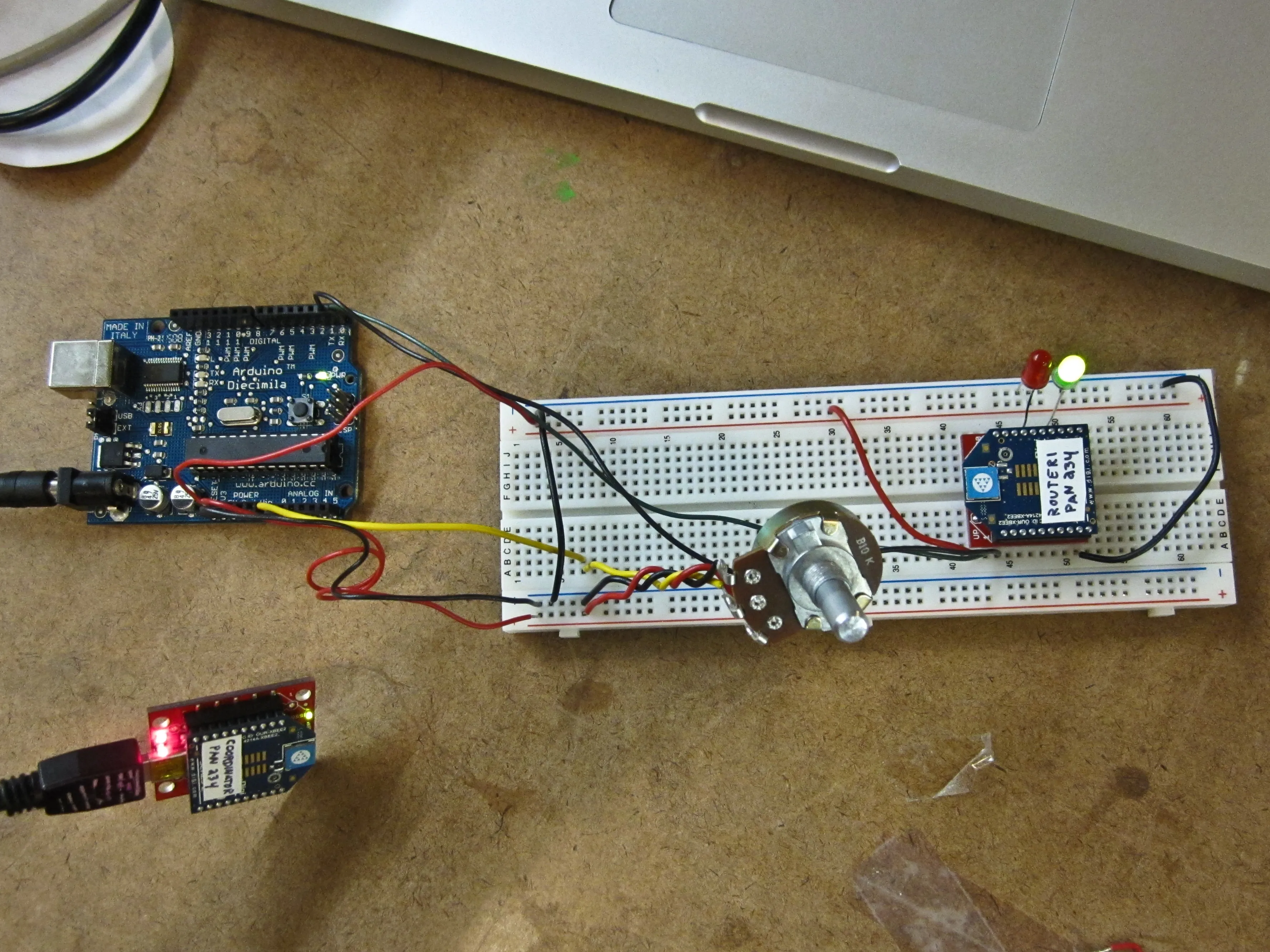
We used XCTU to configure one of the XBees with the “Coordinator AT” firmware and the other with the “Router / End Device AT” firmware. We also made sure that both of the module’s Personal Area Network (PAN) ID’s matched (though we changed them from the default for good measure.) Somehow the firmware upgrade process. Also, the USB Explorer board we used to connect the XBees to serial for firmware updates doesn’t have a reset switch, so resetting the XBee (something XCTU requests pretty often) was accomplished by very carefully shorting the reset pin to ground with a length of wire. This is probably a very bad idea, since shorting the wrong pin could have unexpected consequences. Perhaps as a result of this, one of the firmware update procedures went terribly wrong, and left the XBee bricked. It took some very strange incantations to bring the XBee back to life, but eventually we were able to restore the firmware to the factory settings and proceed as planned.
-
Finally, once all the firmware was in alignment, the “Router” XBee plugged into the arduino started flashing twice a second to indicate that it was connected to the “Coordinator” connected to my laptop. Then, serial started flowing in over the air.
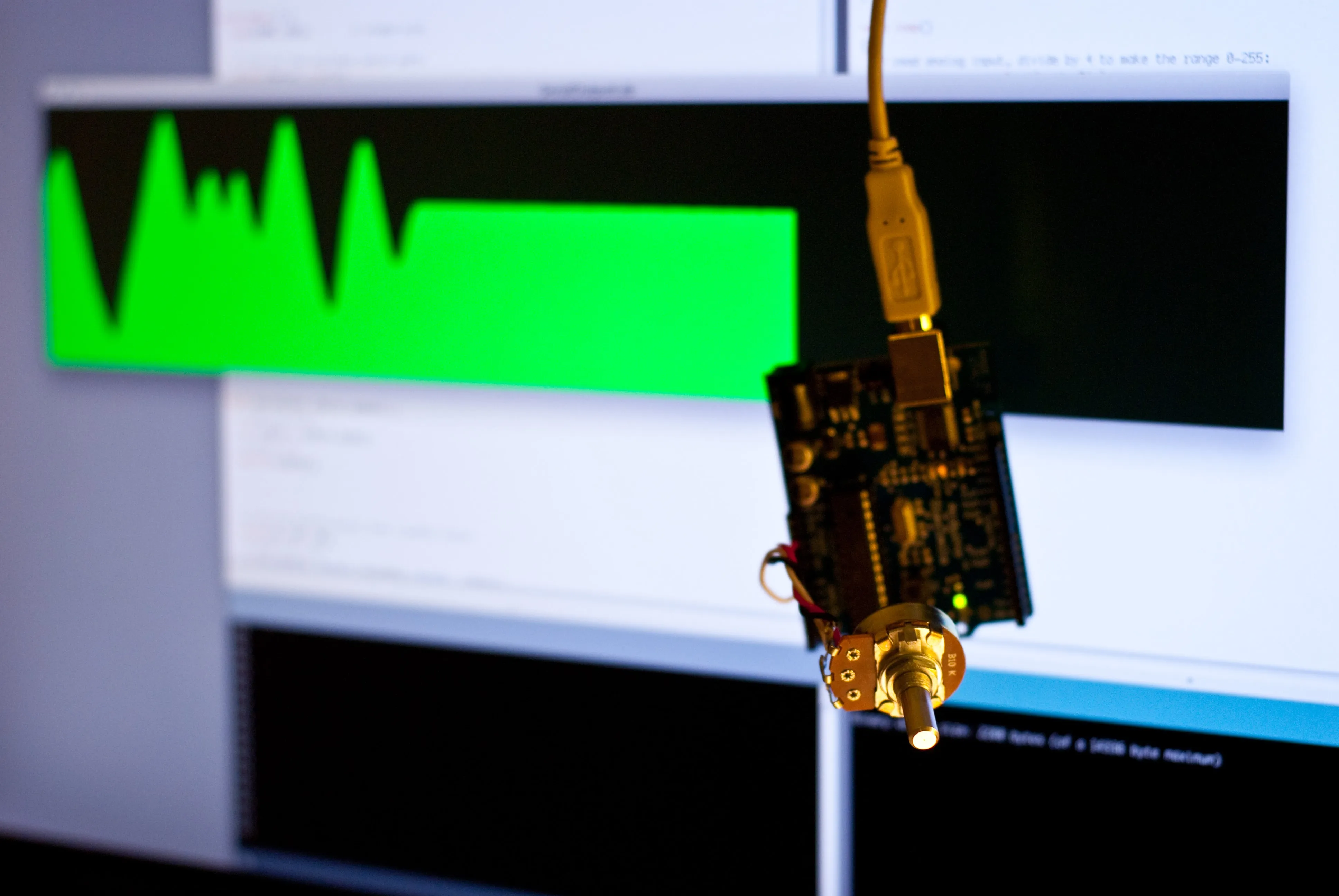
We used a Processing app to graph the signal from the potentiometer. This is where we ran in to some issues that have yet to be resolved… it seems like some data is lost in the signal, as sometimes we get packets of bytes that either terminate prematurely or run too long (past where the newline should have been). We could write some error correction into the Processing side, but before we do that we want to make sure that this issue is not the result of a misconfiguration or some other unexpected variable. (We already tried to change the PAN ID’s in case there was a collision with a nearby XBee, but that didn’t fix the glitches.) There’s also some noticeable lag between turning the pot and the results showing up on the screen. I’m not sure if this is just how things are with wireless, or if we botched a setting somewhere. The video below illustrates the irregular spikes and drops in the serial stream:
Update
Adding c delay(10) to Arduino’s loop seems to have fixed the glitches and lag. That was easy…
Tom shared a few other approaches that could have worked and might still be a good idea to implement: We could have written some kind of error correction… bookend each string of data in unique values, and only use the data if it starts and ends with the bookend values as expected.
Another alternative is to switch to a call-response communication method, so the XBees won’t strain over sending bytes full-bore… instead our Processing app could have mediated the exchange by only requesting data when it was needed.
Recommended resources
Cai Stuart-Maver wrote the life-saving tutorial for Series 2 XBees. (Formerly hosted at humboldt.edu, but the file has since 404d. I’ve mirrored it on my own server in case anyone needs it.)
Rob Faludi knows all.
Justin Downs hosts a bunch of XBee documentation.