This post captures a few notes from a second round of thesis brainstorming.
This time I took a completely different tack, exploring ideas surrounding sustaining the communities and knowledge present on the web without the need for a centralized infrastructure. What might happen, for example, of catastrophic technical or political events shut down ISPs — or if increasing regulation / paranoia leads to national firewalls or censorship?
Could the web be rebuilt with the scraps of hardware most consumers already have on hand? Are Wi-Fi routers, devices, and personal storage ubiquitous enough to patch together a mesh resembling the web as we know it today?
In the context of a thesis project, I envision answers to these questions manifesting as a kind of survival kit. A suitcase full of hard disks and wireless connections, for example, designed to restore fragments of the web to nearby users and act as a node in a broader network of data survivalists.
Here are a few questions to shape early exploration of the idea:
How big is the internet? How about just the text? How much physical space would it take to store a copy of the whole thing?
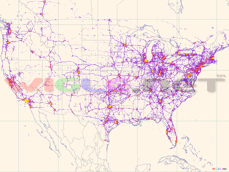
Build or find a wardriving app for the iPhone that will log SSIDs / MAC addresses / geo coordinates while walking around New York. From this data, I could find out how much of the area could (hypothetically) be covered by an ad-hoc mesh-based internet to verify the feasibility of the idea (at least in densely populated areas). WiGLE has been collecting wireless access point info since 2001, and they’ve aggregated and geo-tagged a list of about 27,500,000 Wi-Fi access points so far. Here’s how coverage looks across the United States:
What data do people take with them before they go off-grid?
The subway, for example, is a wifi-free zone… and many riders descend with a few gigabytes of Mp3s at the least. More obsessive types might find ways to cache fragments of the web for consumption sans-connection.
I’d like to take a slightly different tack and give a little background on how computers think about numbers, where abstract numbers end and representational data begins, and how to manipulate this threshold to your advantage.
Binary
This is kind of a basic place to start, but it can be central to preserving your sanity when working on more complicated problems. Everything on your computer can be reduced to bits.
A bit is short for “Binary Digit”, it’s the atom of computation. Alone, a bit can only represent two possible numbers, because there are only two possible ways for a single bit to go: 0 or 1.
To represent larger numbers, we have to stick bits together into longer sequences. Usually, the smallest sequence we’ll work with is 8 bits, or a one byte.
Signed vs. Unsigned
You may have noticed the signed / unsigned keywords stuck before variable type names. This indicates whether or not the first bit in the sequence may be used to represent a number value, or whether it determines if the number is positive or negative. A 0 in the first bit of a signed value means the number is positive, a 1 means it’s negative.
But beware, and int isn’t an int — the number of bytes that make up a particular piece of data is contingent on the particular implementation of the programming language you’re using. In Processing for example, the integer is 32 bits of data, or 4 bytes. It’s also signed, this means it can represent values from -2,147,483,648 to 2,147,483,647. In the Arduino environment, however, an int is just 16 bits, or two bytes, which means you’re limited to representing values between -32,768 to 32,767. A quick way to determine how many values you can represent is the formula 2^(bit length) - 1. (Or 2^(bit length - 1) - 1 for signed types.)
In Processing, the binary() and unbinary() functions are extremely handy for seeing the bits behind the data, and vice versa.
Bits is Bits
If everything on your computer is just bits, then how do we decide what’s an image, what’s a sound file, what’s a text file, etc.?
Basically, these determinations is just oppressive dictums sent down from on-high by your operating system and a cabal of applications. You don’t have to subscribe to these narrow notions… nothing is stopping you from listening to images or reinterpreting music into text.
Cue Processing Demos:
bits_is_bits_cam_to_sound.pde
bits_is_bits_sound_to_image.pde
bits_is_bits_text_to_sound.pde
Really Big Numbers
In Processing, the largest number you can work with in the documented data types is a “long” — which is 64 bits of signed data, giving you 9,223,372,036,854,775,807. Lame. So what happens when you need to work with bigger numbers?
The way around these limitations is to use something called arbitrary precision arithmetic. Arbitrary precision arithmetic basically uses byte arrays of indeterminate (and conceptually infinite) length to allow you to do math with incredibly large numbers. They’re going to be much, much slower than using your programming language’s native data types, but when you need to work with really big numbers it’s a handy thing to have around.
The gold standard open-source option is the The GNU MP Bignum Library. There’s a big number library built into Java (and therefore Processing), you just need to explicitly load it and deal with its weird syntax. If you need one for ActionScript 3, talk to me. (Links pending!)
Here’s a quick example of breaking the 9 quintillion barrier in Processing:
import java.math.BigInteger;void setup() { BigInteger a = new BigInteger("9223372036854775807"); BigInteger b = new BigInteger("9223372036854775807"); BigInteger sum = a.add(b); // Decimal representation println(sum); // Binary representation println(sum.toString(2));}
So why bother with this? If you can manipulate bit strings of arbitrary length, you can start to do math with pieces of data large enough to have representational value.
Cue another processing demo: bits_is_bits_every_image.pde
Gratuitous Tips
You can do basic math in the Mac’s spotlight search bar, command-space brings it up quickly.
The built in mac calculator has a programmer mode which shows you different representations of the same number. Pull up the calculator and press command-3 to switch into programmer mode.
Wolfram Alpha is super handy for doing arbitrary-precision calculations, balancing equations, graphing stuff, etc.
Hex Fiend is a great, free hex editor for the mac that makes it easy to pry into the numbers behind any file on your computer.
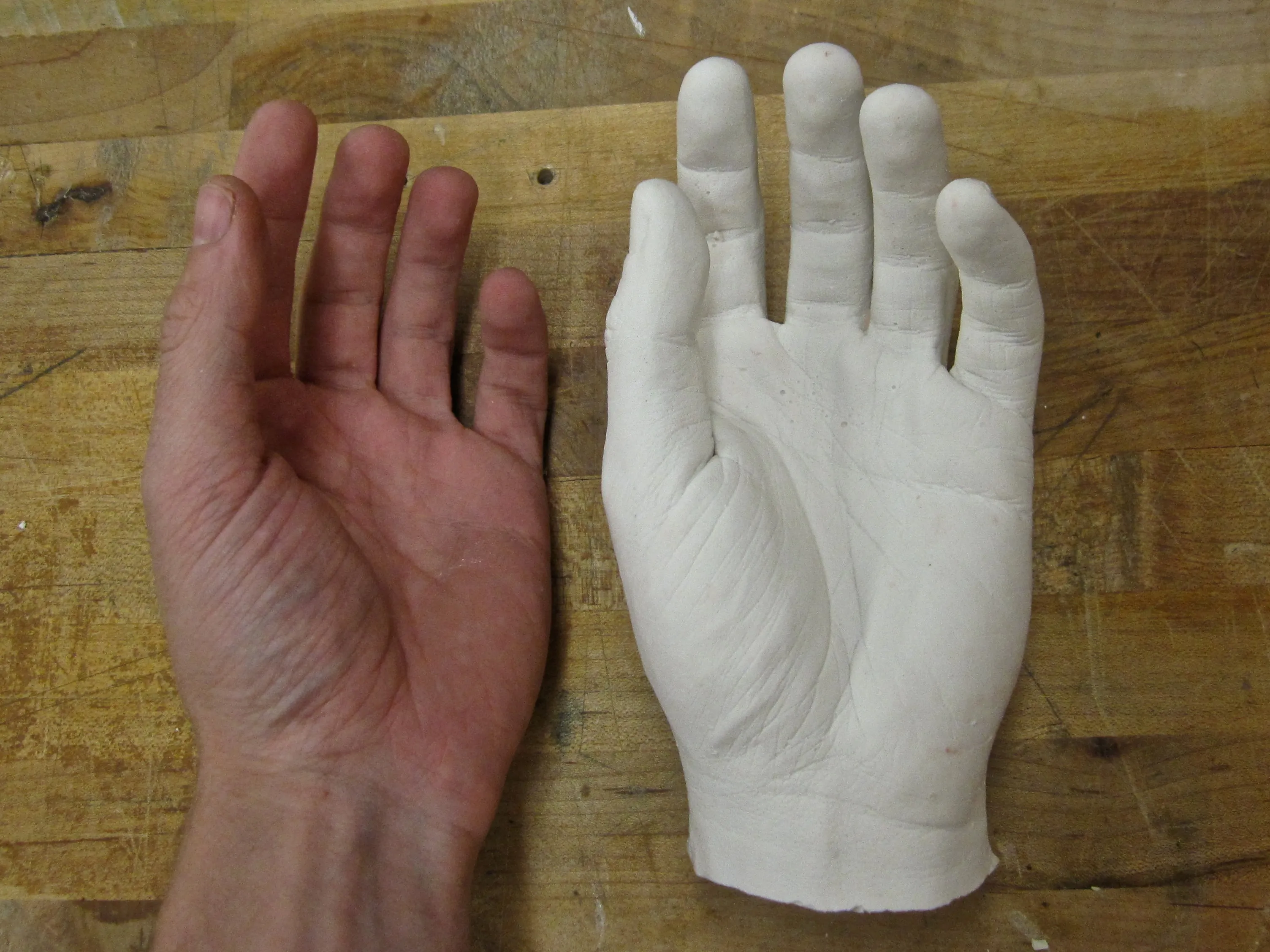
This week’s materials assignment called for the “hello world” of mold making: the hand casting.
For the mold, I used MoldGel Regular Set alginate, and the finished casting was set in pottery plaster. The process went smoothly, for the most part, but a few things could have gone more smoothly:
Hand-mixing even small quantities of alginate is not such a good idea. I was left with lumps and bubbles that showed up as pits in the plaster casting.
A 1 mix of alginate to water by volume leaves the alginate way too thick, and since it sets so quickly there’s not a lot of time to revise the ratio before you have to pour. Better to listen to the product’s information sheet than vague rules-of-thumb.
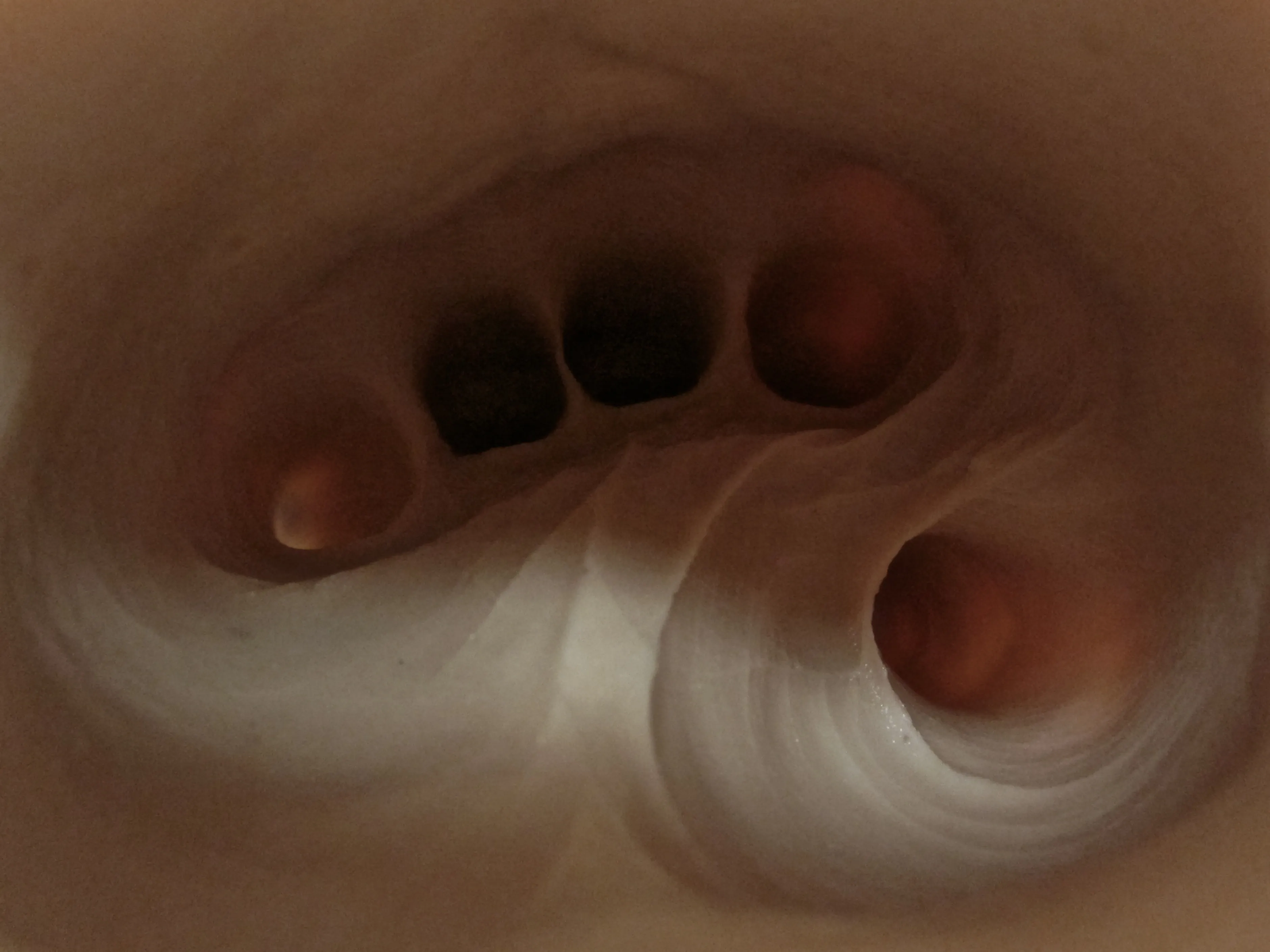
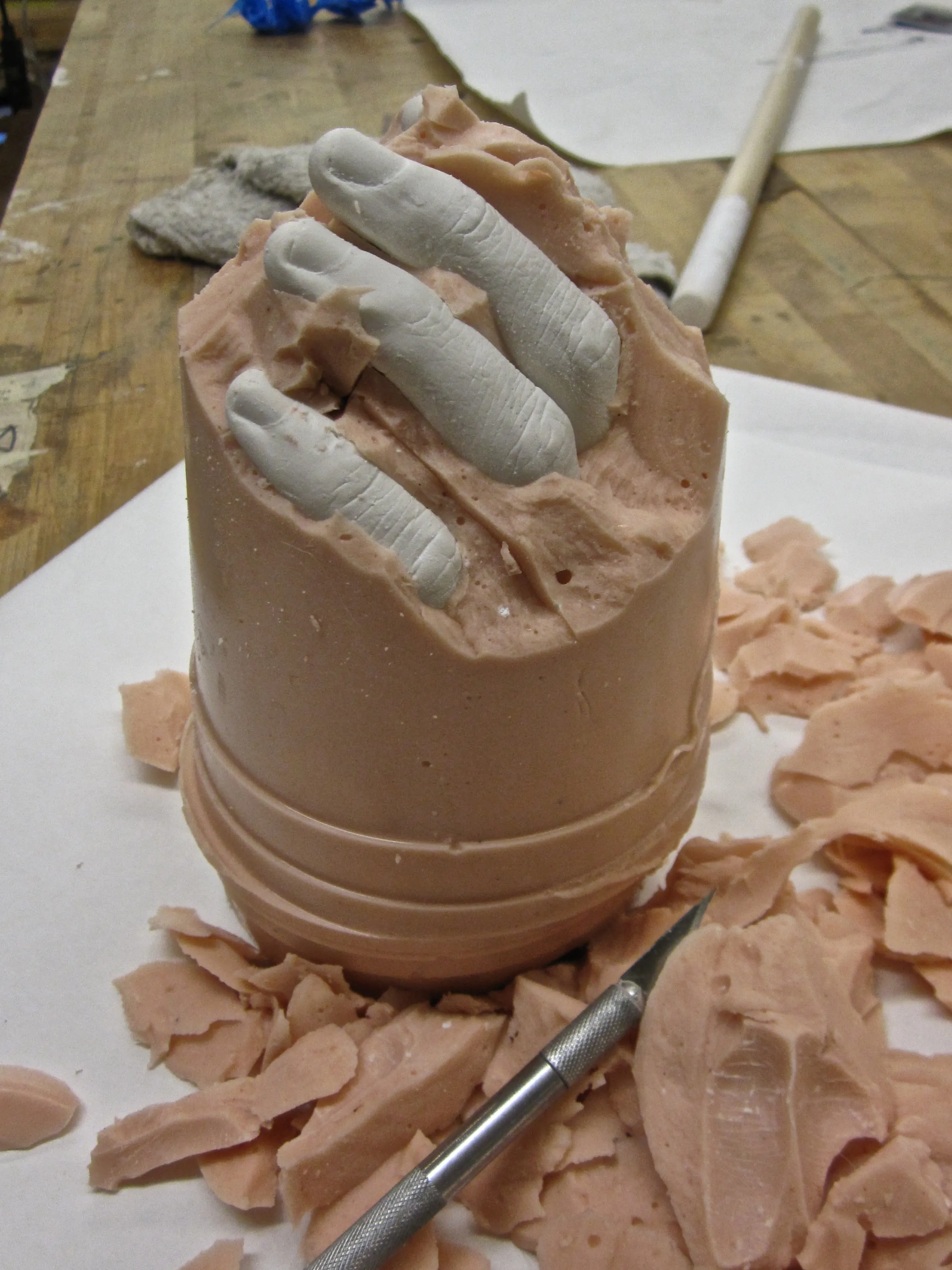
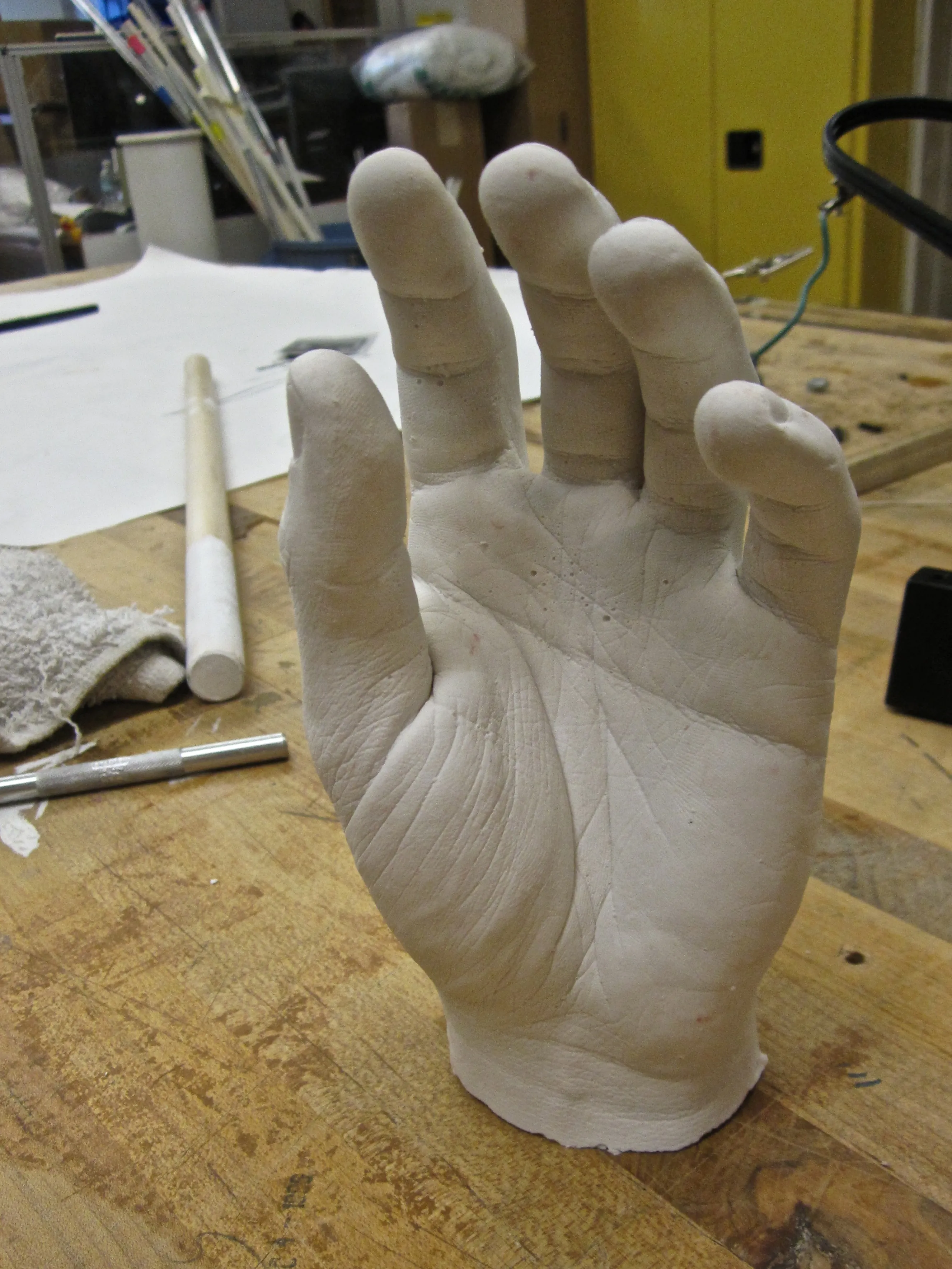
The (unsettling?) photo above shows the inside of the alginate mold after I removed my hand. The photos below show the finished casting in various stages of removal from the mold.
A few semesters ago I uploaded some flawed stepper-control code to an Arduino that resulted in a pleasing and rhythmic failure-loop as the target stepper motor cycled between working and non-working states. I made a note of the code and shelved further exploration for a rainy day.
My instrument sketch for NIME revisits this phenomenon and explores how the sounds of electrical signals driving a mechanical output diverge from the actual mechanical output.
I’m particularly interested in the borderlands between mechanical and electrical “work”. Motors and generators are among the most common means of translating between electrical and mechanical states — but stepper motors are particularly rich territory from an acoustic point of view because they’re driven by more complex signals than typical DC motors. By using a stepper motor’s control signals as an audio source, we can listen in on the instructions before they’re converted into mechanical output. Conversely, miking the stepper motor itself allows us to hear the motor’s interpretation / misinterpretation of those signals as the clunks and vibrations mechanical motion.
So, I created DRÖNA, a testbed for exploring these thresholds and ideas in real time.
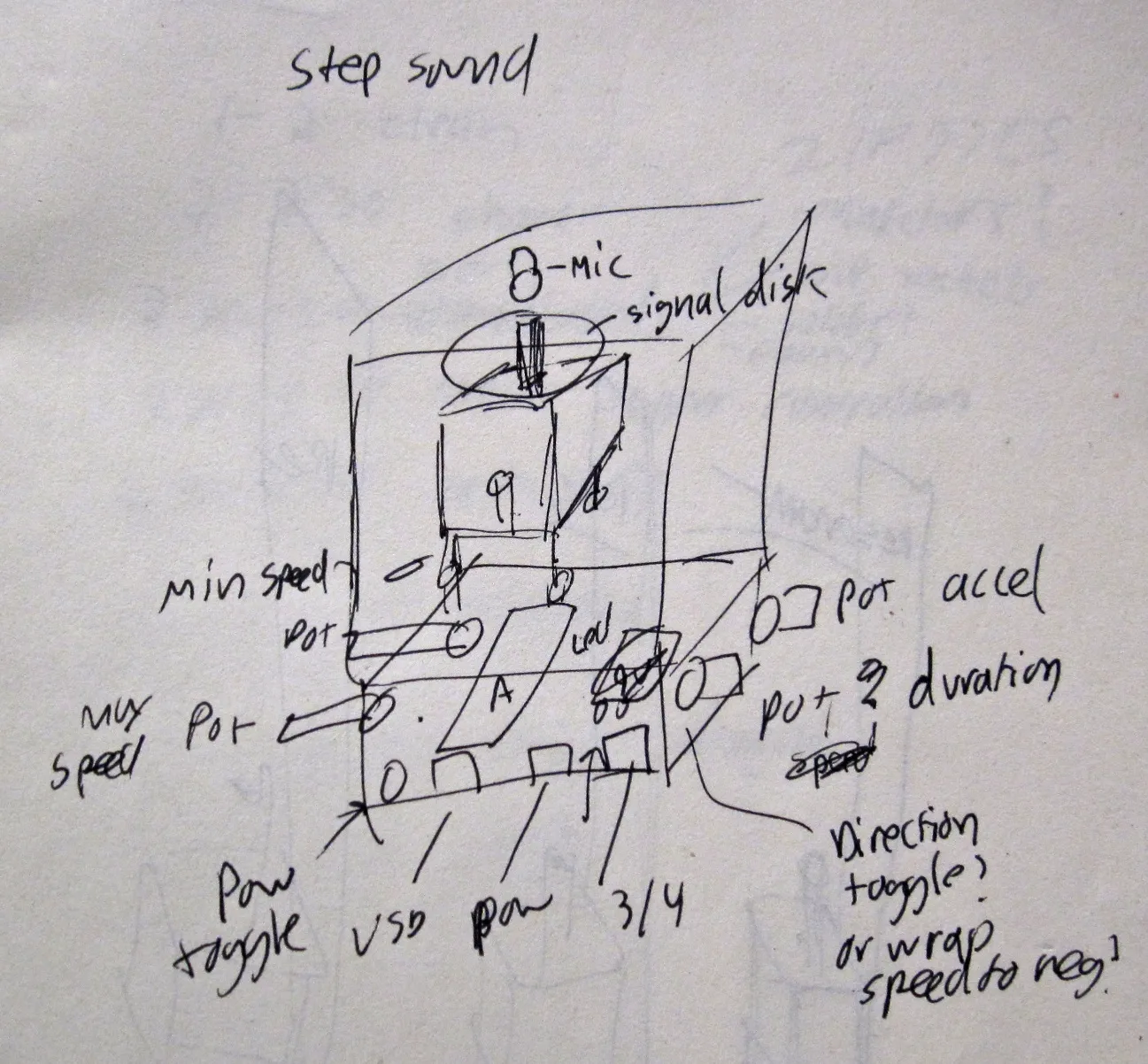
Design
The initial sketch, below, shows the basic idea of a microphone picking up sounds generated by a stepper motor. In turn, the code driving the stepper is controlled by a number of potentiometers to allow for munging with the speed of rotation, delay periods, random jitter, and that sort of thing.
As a NIME project the design is lacking a bit, since the actual process of interaction is mostly relegated to knob-twiddling — only marginally better than hovering over a laptop from a performance standpoint. I tried to work around this slightly by attaching a large wheel to the stepper motor which can be grabbed and manipulated directly to interfere with the electrical (and therefore the audio) signals coming out of the stepper.
Since this was just a first exploration of the kind of sounds I could generate (I wasn’t sure what I would be dealing with), the design doesn’t take many risks in the mode-of-interaction department. My hope is that after experimenting with this knob-based version, alternative and more representational approaches to controlling the stepper motor would become evident.
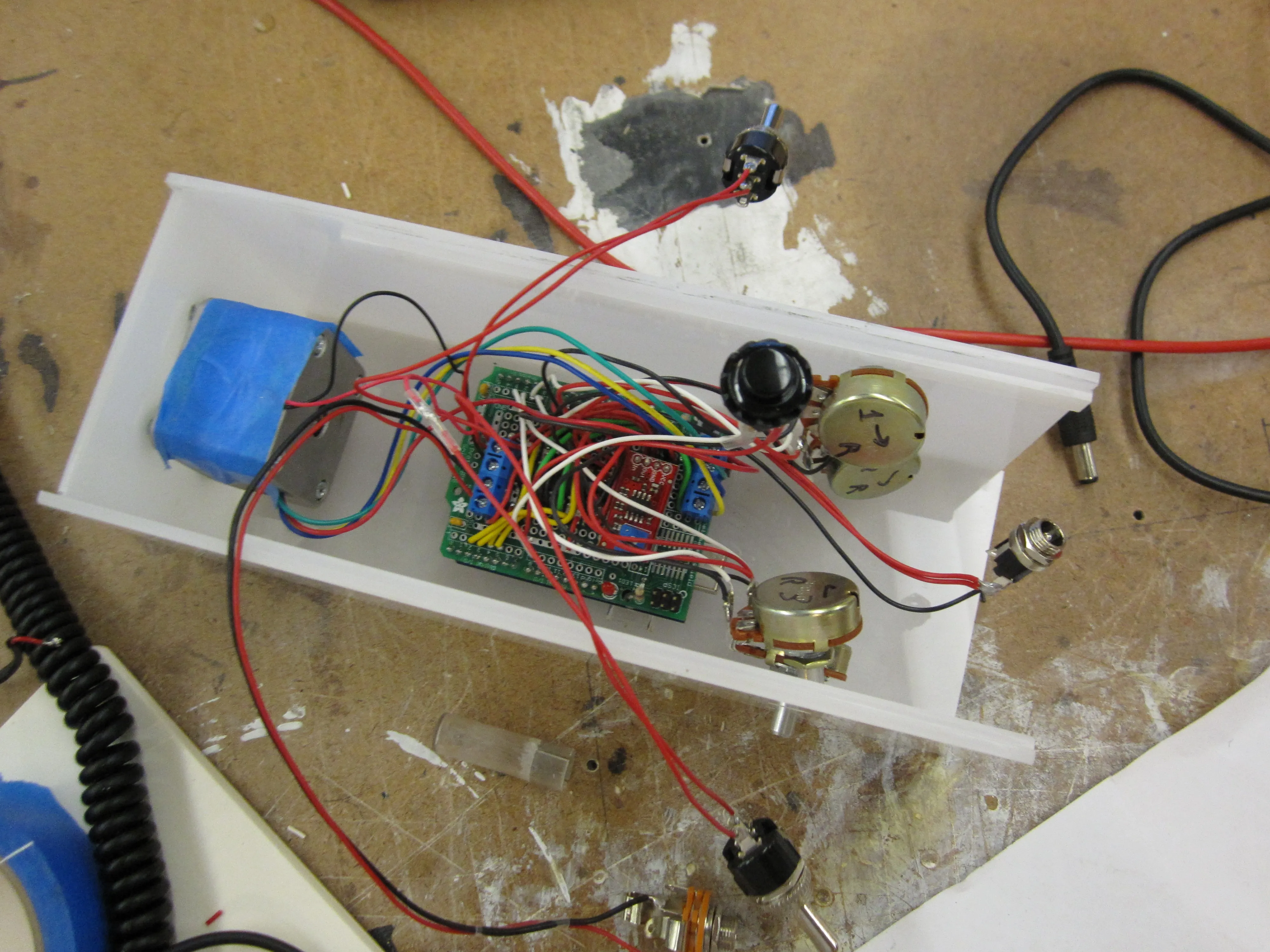
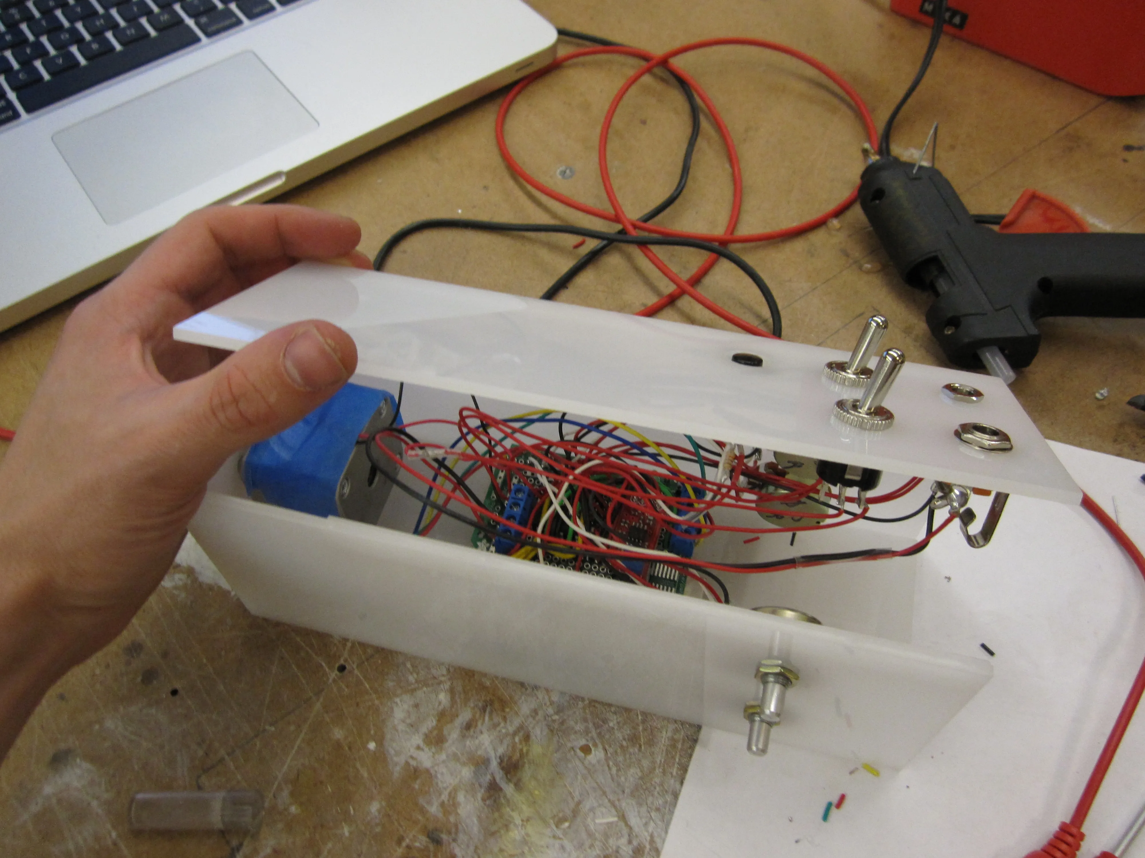
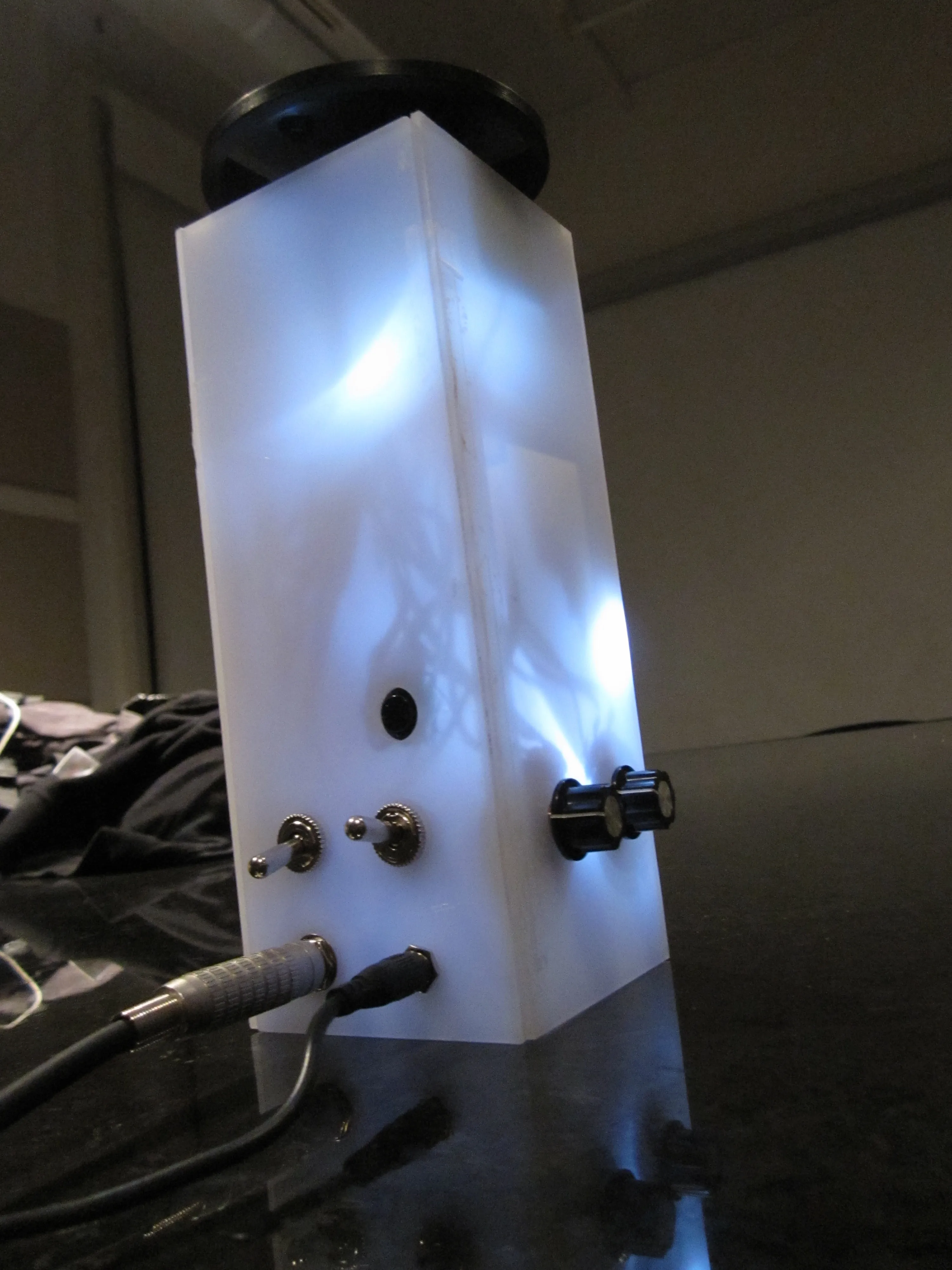
The enclosure was designed out of translucent plastic so light from a series of LEDs attached to the audio output could show through. I also needed enough surface area to comfortably mount the four steppers, two toggles, pushbutton, and power / audio jacks. I considered going with clear plexi instead, to make clear the relationship between the stepper and the contact mic, but the electronics inside turned into such a rat’s nest of leads that I decided to tone down this aspect a bit. A two-tone enclosure might have been ideal, to reveal the stepper and contact mic behind clear plexi while keeping the rest of the electronics hidden behind translucent white plexi.
Build Process
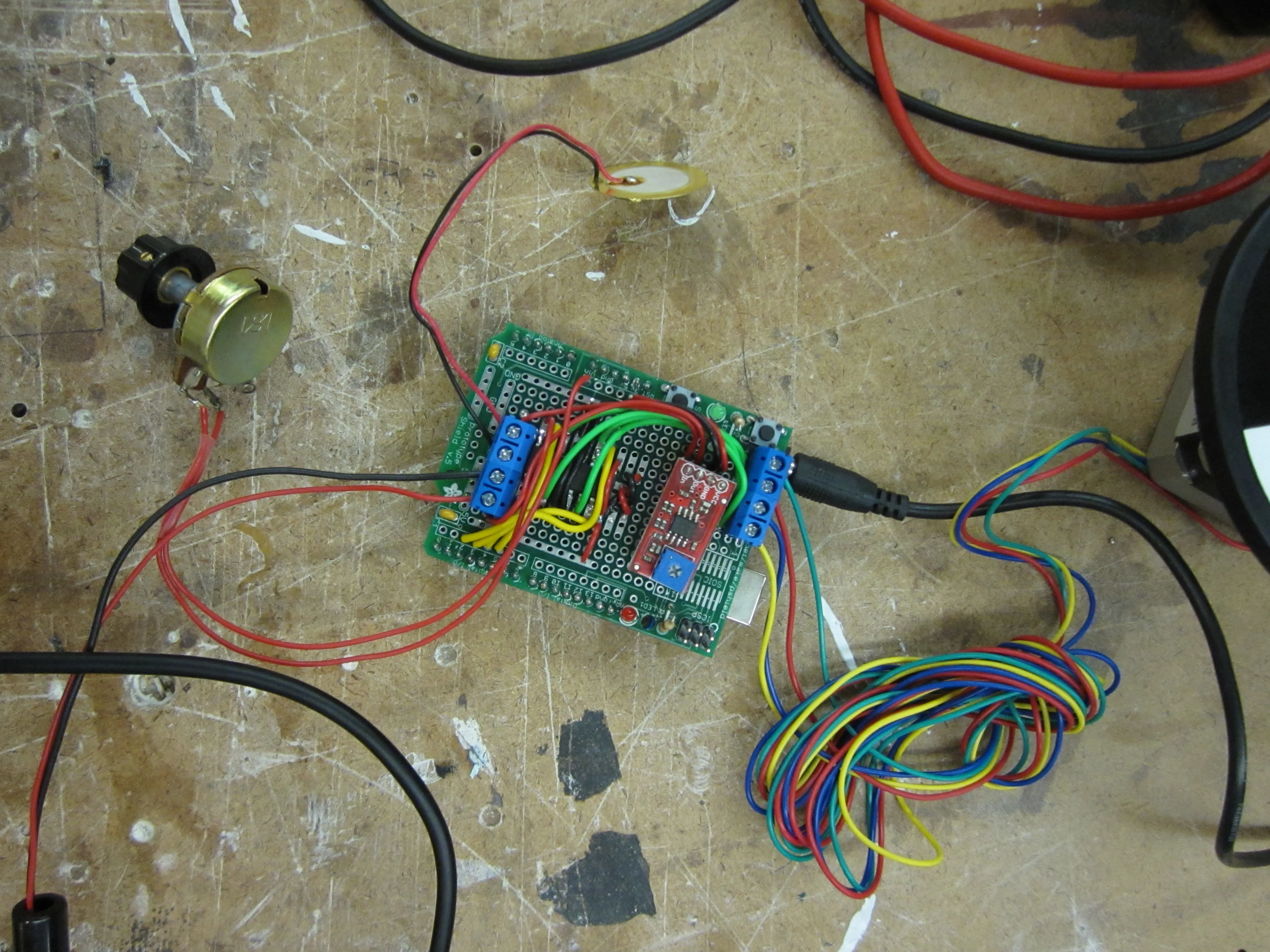
With the basic design in mind, I finalized how the circuit was going to work. The final layout of components is something like this:
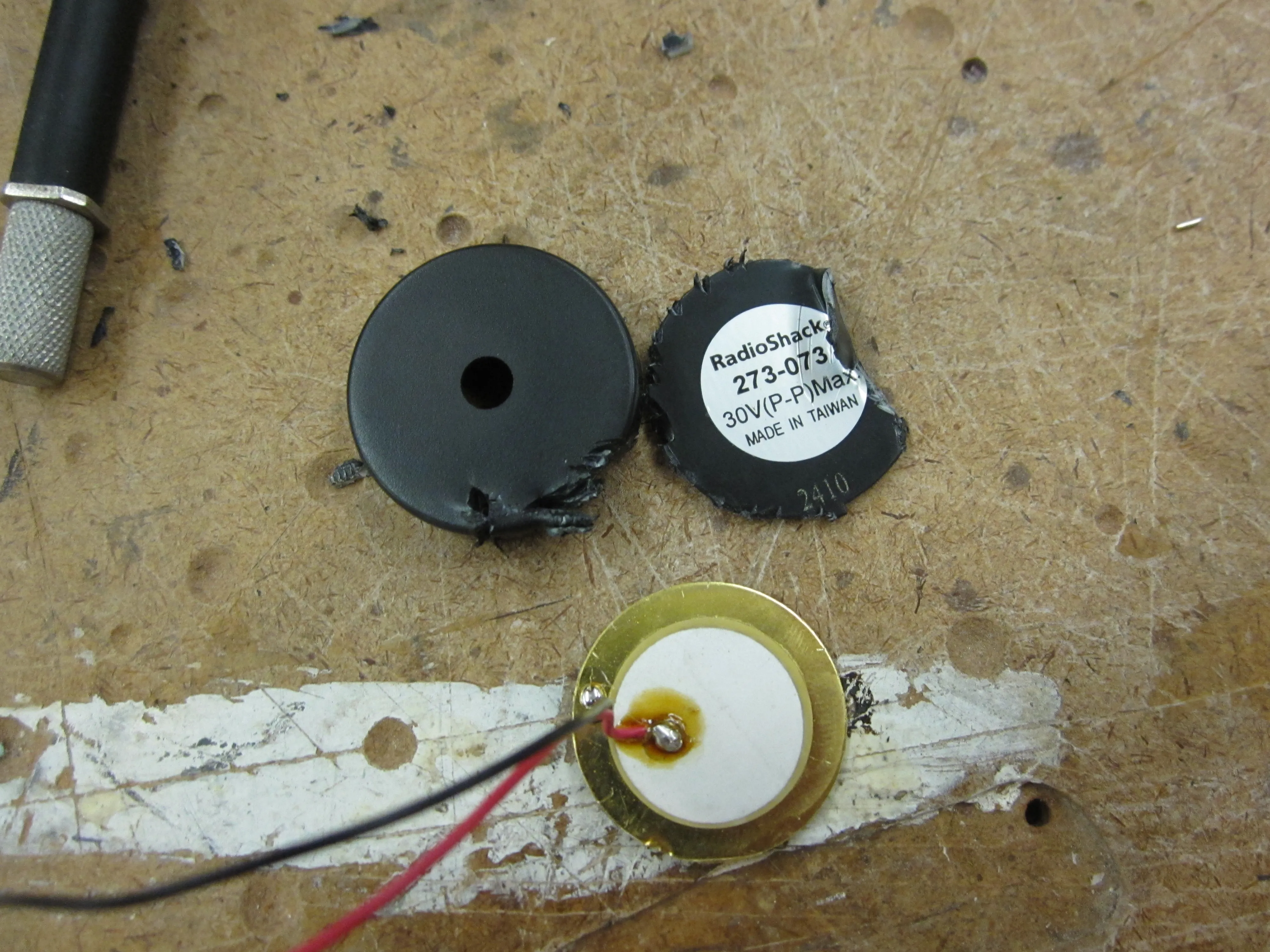
I didn’t have a contact mic handy, but fellow-NIMEr Igal Nassima pointed me to a tutorial on adapting cheap Piezo transducers for use as contact mics. Perfect.
I used an Adafruit Proto Shield to keep the H-bridge for the stepper and the rest of the electronics in one place.
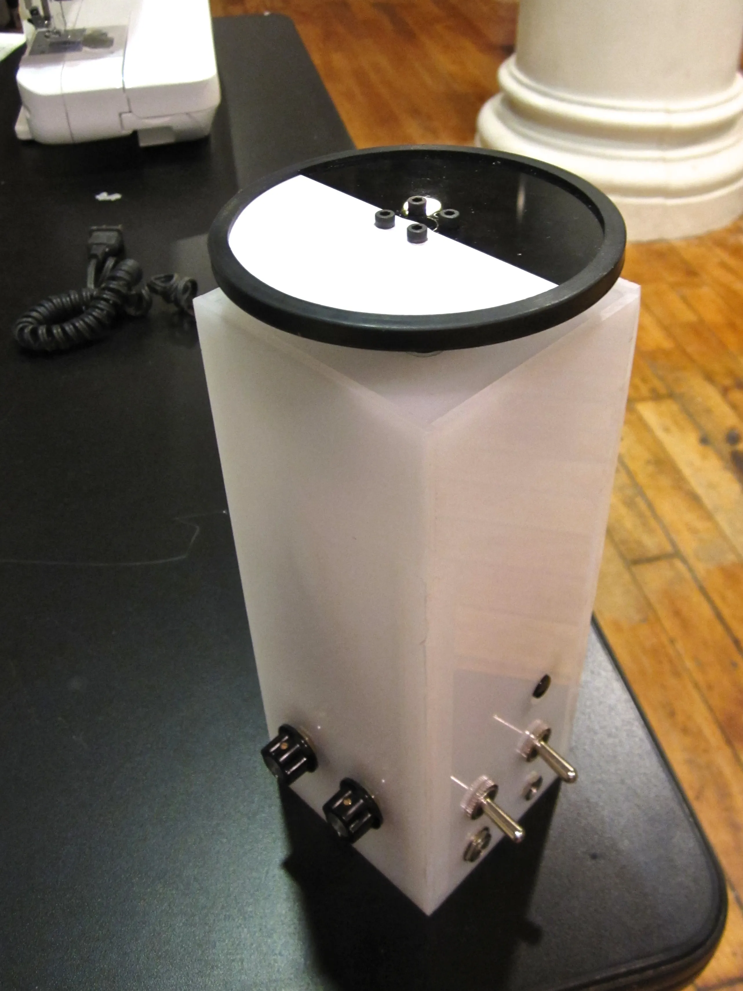
Next came the enclosure, basic milky-white 1/8” acrylic glued together to form a box. There’s another post documenting the box build in detail. DRÖNA owes its name to the enclosure design, which ended up looking unsettlingly similar to an IKEA product.
Securing the contact mic to the stepper was particularly problematic. It sounded great when held in place against the stepper by hand, but every other means of attachment resulted in a less compelling sound. I tried gaffers tape, hot glue, zip ties, and a friction-based fit against the side of the box with a wedge of foam. Nothing ended up sounds quite right, but I settled on the foam wedge.
The wheel I attached to the stepper was left over from a past robotics project. To make its rotation more visible, I covered half of it with white contact paper.
That’s about it for the fabrication.
The Code
The code was relatively simple, the stepper library included with the Arduino IDE takes care of generating the signals that drive the motor. The rest of the code just involves mapping analog values from the four potentiometers to various aspects of the stepper’s motion.
The finished instrument is demonstrated in the video at the top of this post. It ended up looking like this:
And sounding like this:
The sound is moderately insufferable, less so if you’re predisposed to grating and glitchy sounds. For the most part, the direct digital mode (grabbing audio from the signal between the H-bridge and the stepper) is a square wave of various intervals — although analyzing the wave itself shows that the actual signal is closer to a saw-tooth due to slop in the circuit. The analog mode, where audio comes from the contact mic attached to the stepper itself, makes for a much messier signal that gets more interesting if you stall the stepper by hand or adjust the knobs to force the stepper into an overspeed condition.
Problems:
I set up the circuit so that you could listen to both the analog feed and the digital feed simultaneously, but the digital feed is so much cleaner / louder that it completely drowns out the analog signal. (Didn’t have time to set up more precise mixing control.) Perhaps it would be more interesting to take the difference of these two signals instead of merely mixing them together.
Control is a real issue. The potentiometers don’t actually control discrete elements of the sound, each setting influences / is subject to influence from the other controllers. It’s a lot to keep track of. Furthermore, the speed at which you turn the knobs can influence the final state. For example, if you turn the stepper speed knob too quickly, the motor will stall — which means you can end up with different sounds from identical knob settings.
The output signal is lopsided — it’s actually more of a DC signal than an AC signal, so it doesn’t end up using the full dynamic range available by the capture device. I should clean up the circuit to fix this.
Possible Improvements:
Using a more robust stepper library than the one that ships with Arduino could allow for micro-stepping and other tricks which could have interesting acoustic outcomes.
Precise mixing between the analog / digital sound sources.
Some kind of feedback loop, e.g. using the analog signal from the stepper’s contact mike to munge the stepper control signal.
Overall, the acoustic outcome was less interesting and more out of control than I had hoped. If I was to explore the DRÖNA concept further, I would try to do more on the analog front — perhaps experimenting with resonances from different enclosure sizes, motor sizes, etc. There are also other feedback loops where the divergence between control signal and generated output might create interesting effects. (For example, the difference / delay between commands sent to an LED and light picked up from a nearby LDR.)
The full list is probably long enough to seed an infinite supply of convincing IKEA product titles… in case anyone’s so inclined. Until then, the official IKEA naming algorithm is documented on Wikipedia.