Background
A few semesters ago I uploaded some flawed stepper-control code to an Arduino that resulted in a pleasing and rhythmic failure-loop as the target stepper motor cycled between working and non-working states. I made a note of the code and shelved further exploration for a rainy day.
My instrument sketch for NIME revisits this phenomenon and explores how the sounds of electrical signals driving a mechanical output diverge from the actual mechanical output.
I’m particularly interested in the borderlands between mechanical and electrical “work”. Motors and generators are among the most common means of translating between electrical and mechanical states — but stepper motors are particularly rich territory from an acoustic point of view because they’re driven by more complex signals than typical DC motors. By using a stepper motor’s control signals as an audio source, we can listen in on the instructions before they’re converted into mechanical output. Conversely, miking the stepper motor itself allows us to hear the motor’s interpretation / misinterpretation of those signals as the clunks and vibrations mechanical motion.
So, I created DRÖNA, a testbed for exploring these thresholds and ideas in real time.
Design
The initial sketch, below, shows the basic idea of a microphone picking up sounds generated by a stepper motor. In turn, the code driving the stepper is controlled by a number of potentiometers to allow for munging with the speed of rotation, delay periods, random jitter, and that sort of thing.
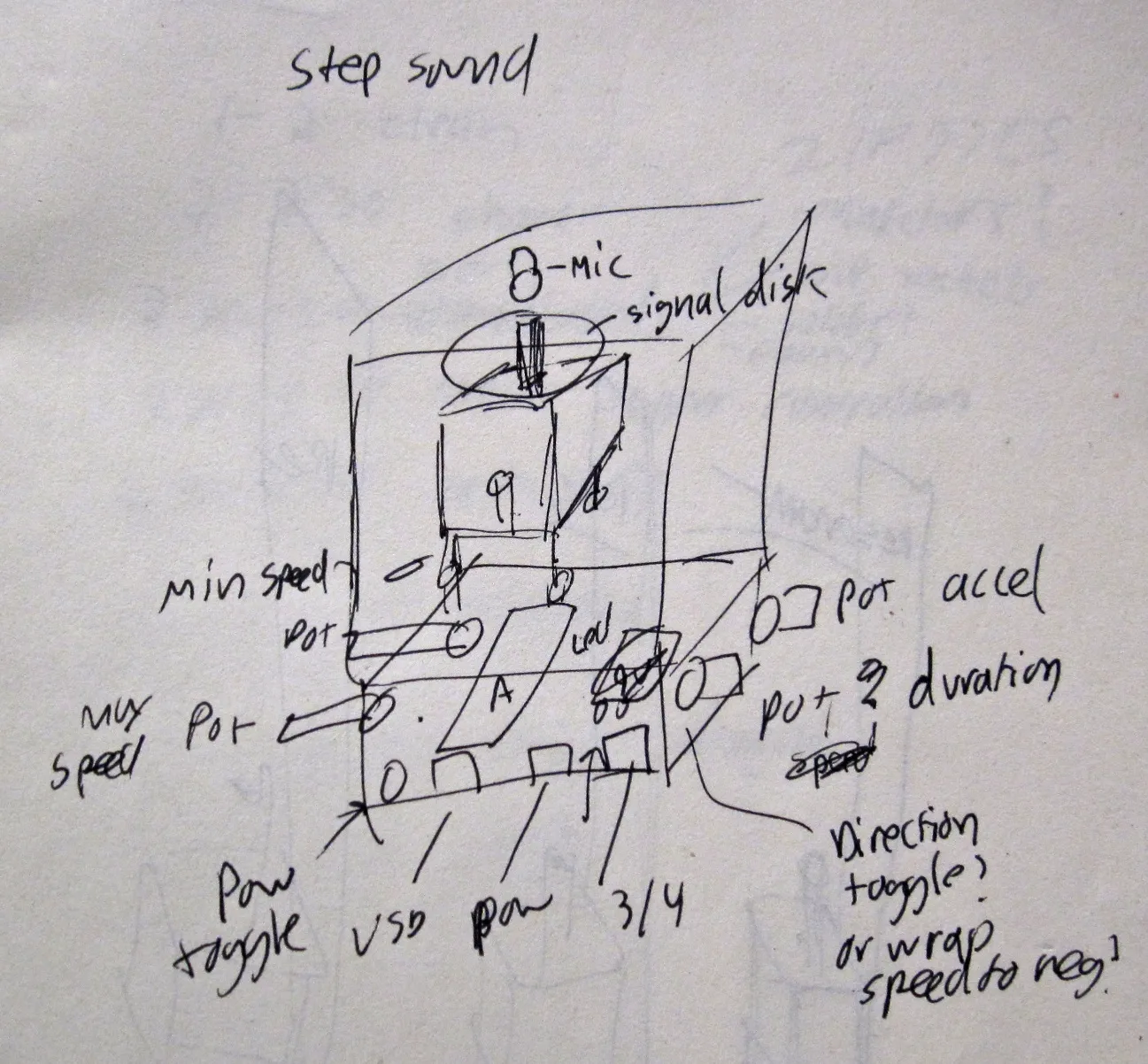
As a NIME project the design is lacking a bit, since the actual process of interaction is mostly relegated to knob-twiddling — only marginally better than hovering over a laptop from a performance standpoint. I tried to work around this slightly by attaching a large wheel to the stepper motor which can be grabbed and manipulated directly to interfere with the electrical (and therefore the audio) signals coming out of the stepper.
Since this was just a first exploration of the kind of sounds I could generate (I wasn’t sure what I would be dealing with), the design doesn’t take many risks in the mode-of-interaction department. My hope is that after experimenting with this knob-based version, alternative and more representational approaches to controlling the stepper motor would become evident.
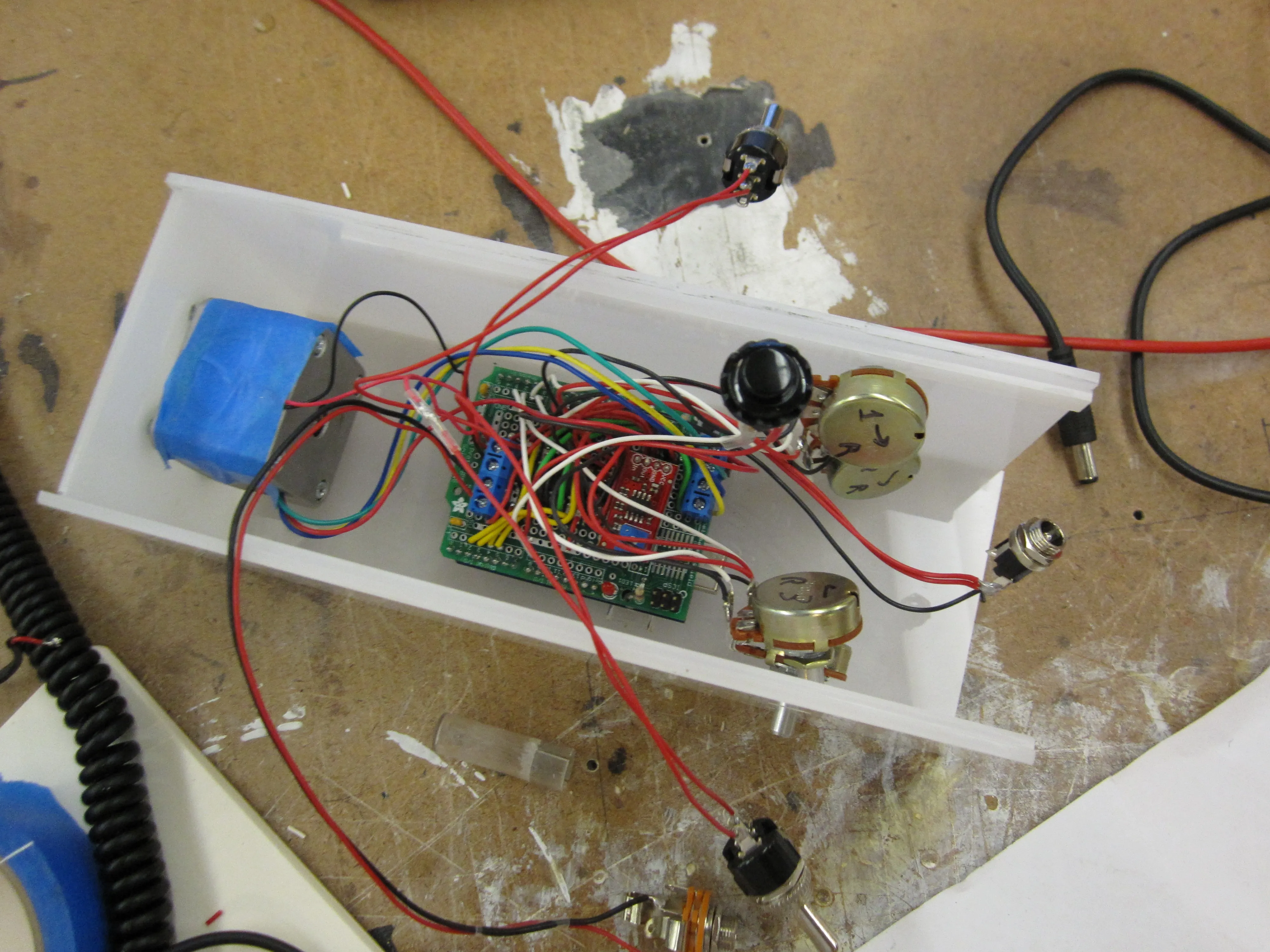
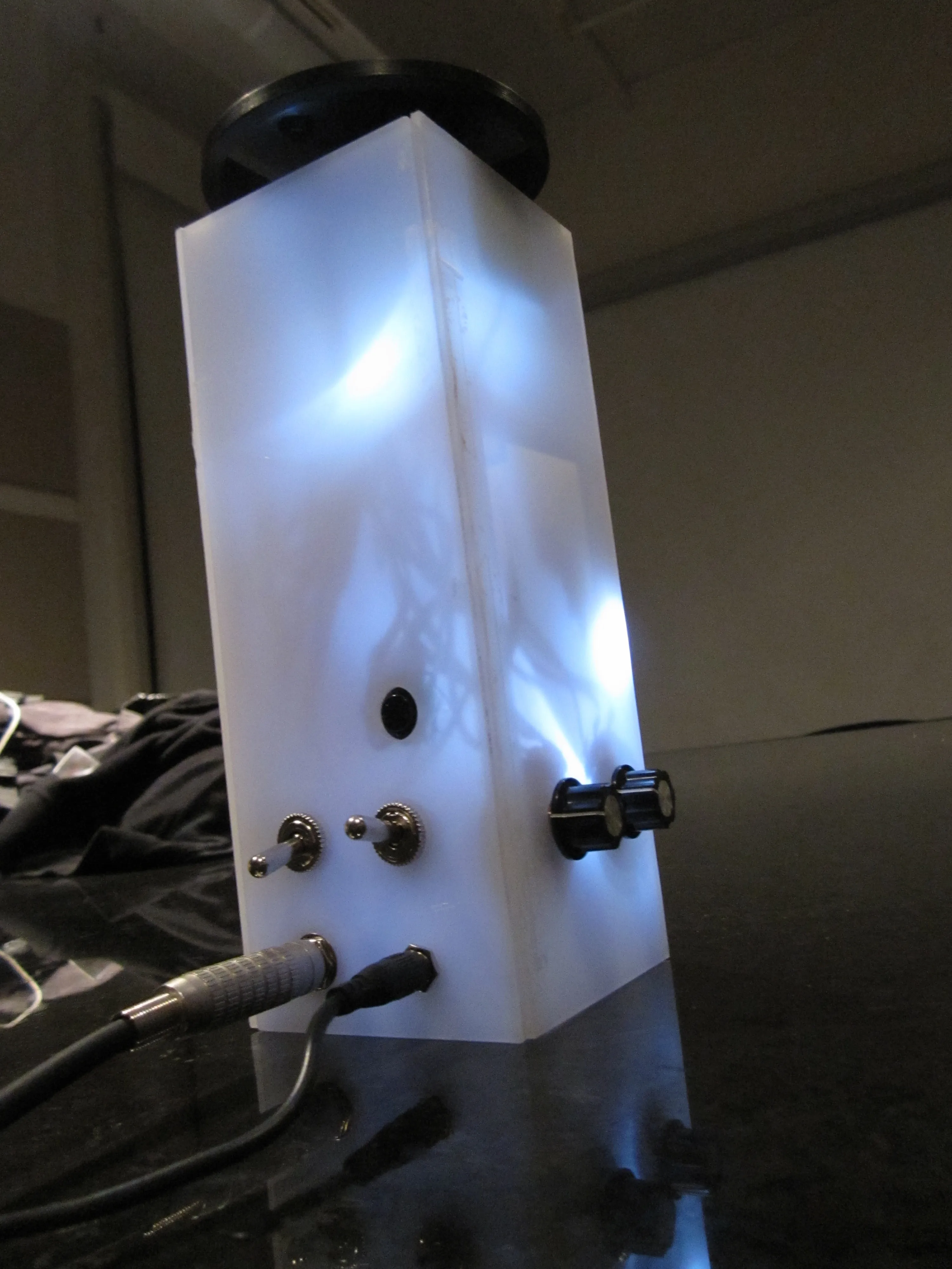
The enclosure was designed out of translucent plastic so light from a series of LEDs attached to the audio output could show through. I also needed enough surface area to comfortably mount the four steppers, two toggles, pushbutton, and power / audio jacks. I considered going with clear plexi instead, to make clear the relationship between the stepper and the contact mic, but the electronics inside turned into such a rat’s nest of leads that I decided to tone down this aspect a bit. A two-tone enclosure might have been ideal, to reveal the stepper and contact mic behind clear plexi while keeping the rest of the electronics hidden behind translucent white plexi.
Build Process
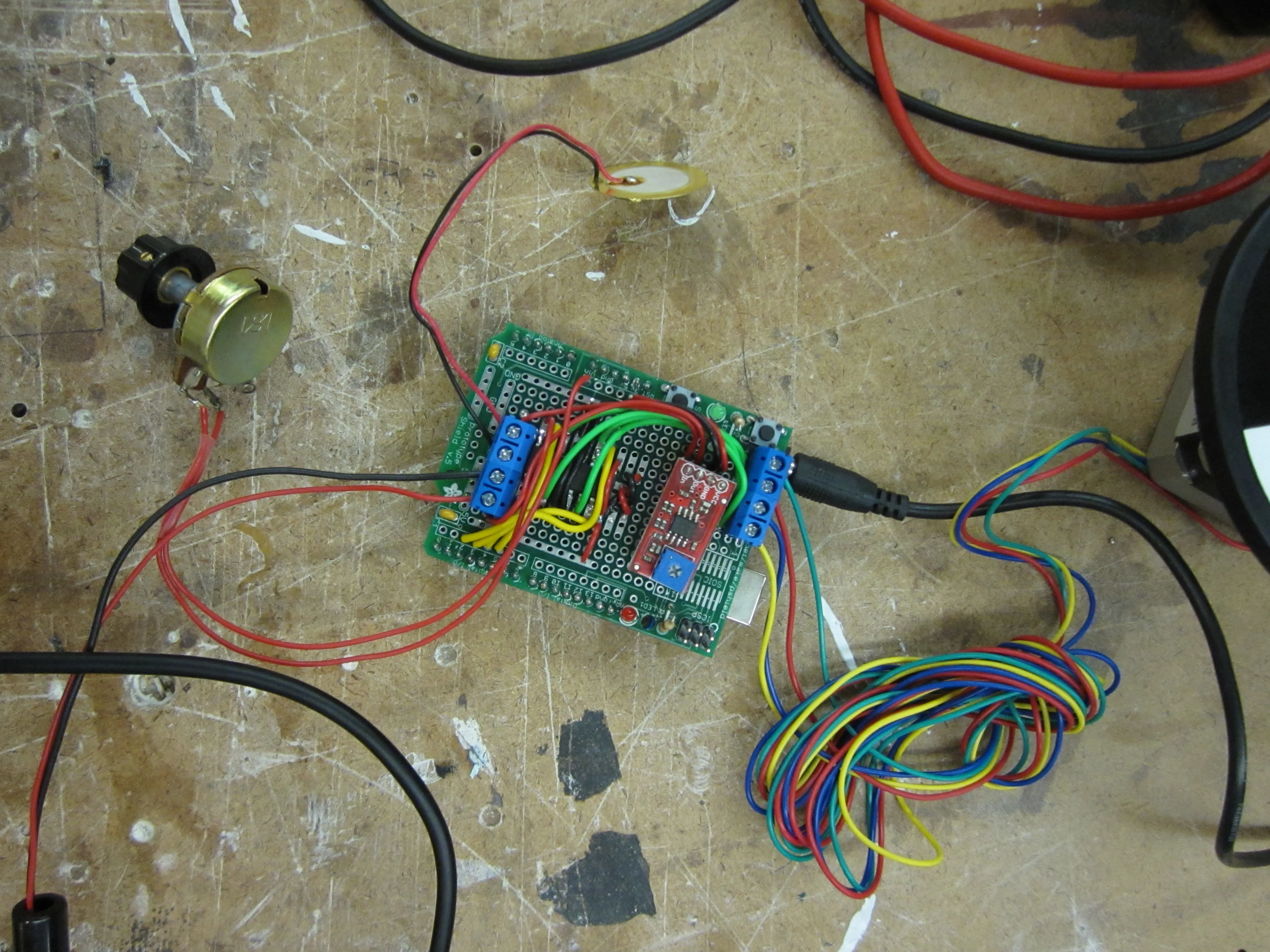
With the basic design in mind, I finalized how the circuit was going to work. The final layout of components is something like this:

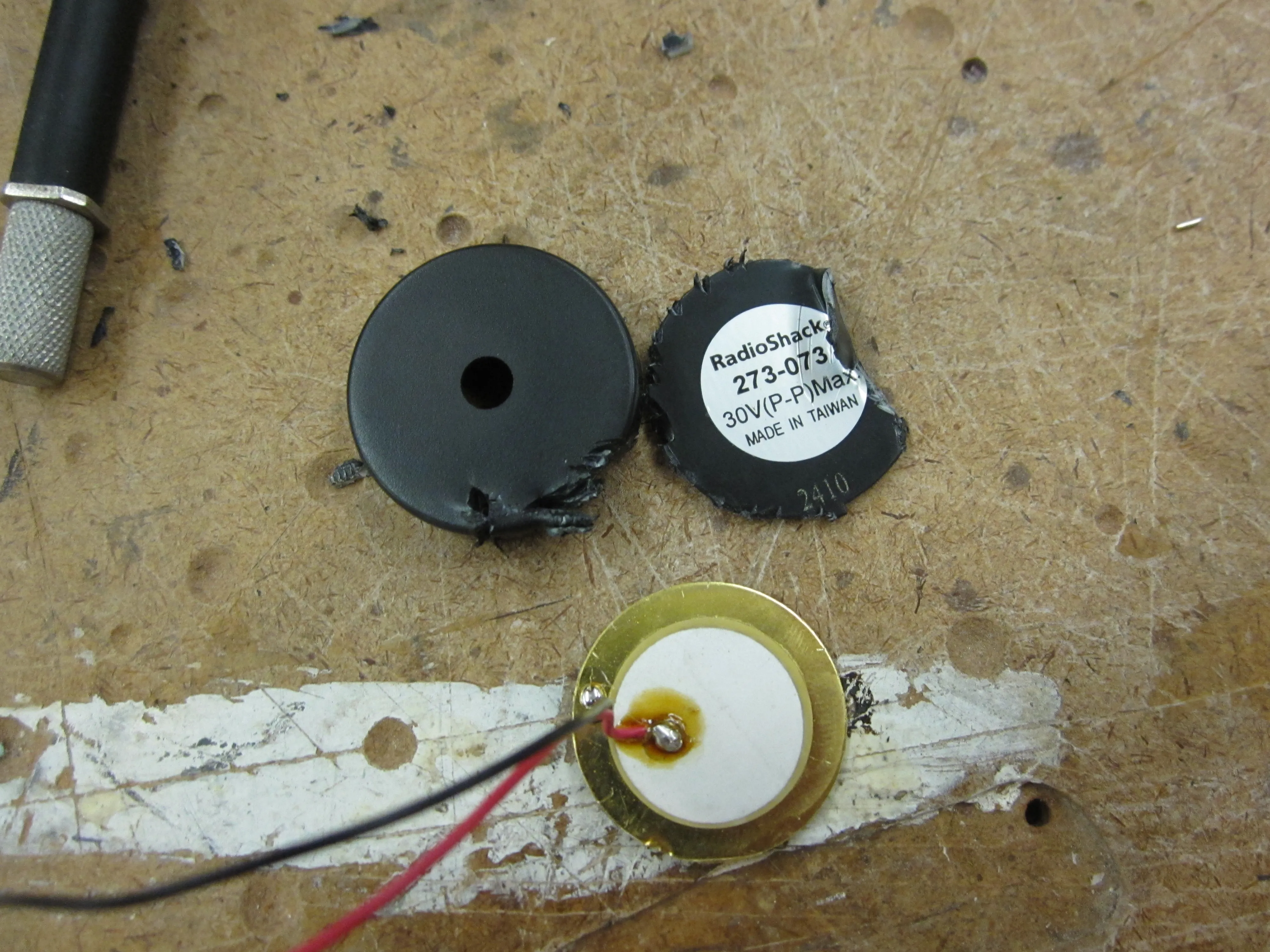
I didn’t have a contact mic handy, but fellow-NIMEr Igal Nassima pointed me to a tutorial on adapting cheap Piezo transducers for use as contact mics. Perfect.
I used an Adafruit Proto Shield to keep the H-bridge for the stepper and the rest of the electronics in one place.
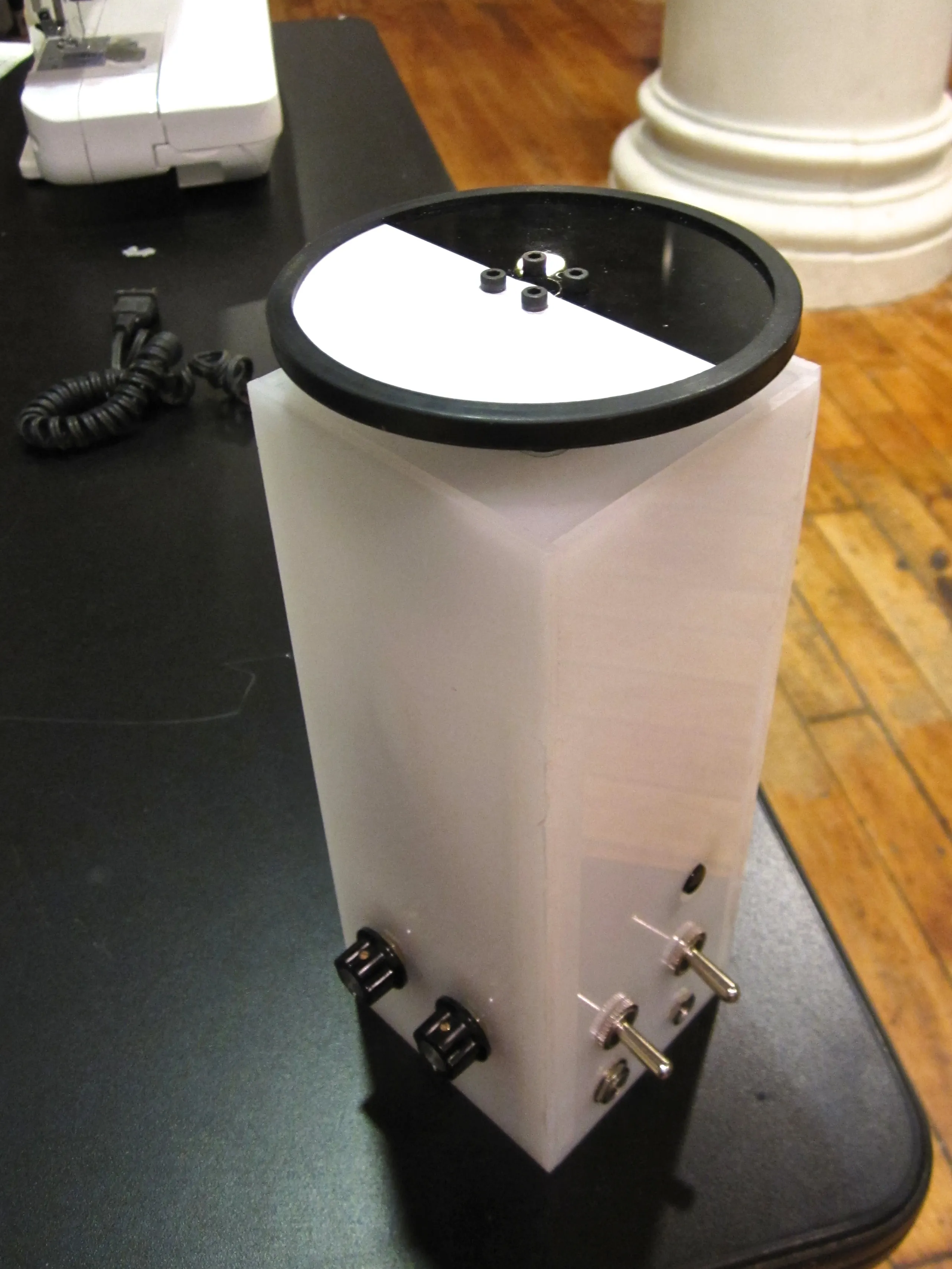
Next came the enclosure, basic milky-white 1/8” acrylic glued together to form a box. There’s another post documenting the box build in detail. DRÖNA owes its name to the enclosure design, which ended up looking unsettlingly similar to an IKEA product.
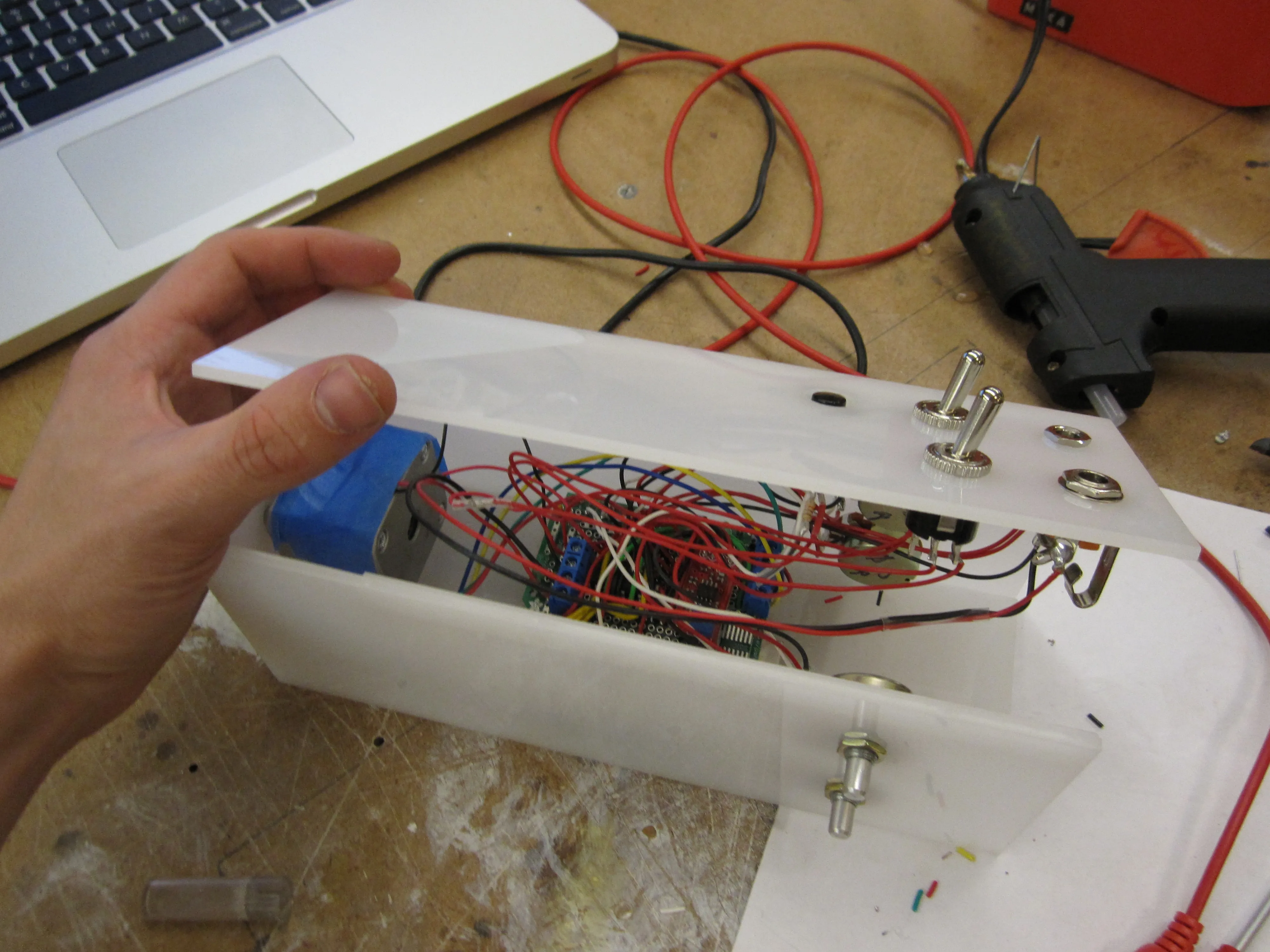
Securing the contact mic to the stepper was particularly problematic. It sounded great when held in place against the stepper by hand, but every other means of attachment resulted in a less compelling sound. I tried gaffers tape, hot glue, zip ties, and a friction-based fit against the side of the box with a wedge of foam. Nothing ended up sounds quite right, but I settled on the foam wedge.
The wheel I attached to the stepper was left over from a past robotics project. To make its rotation more visible, I covered half of it with white contact paper.
That’s about it for the fabrication.
The Code
The code was relatively simple, the stepper library included with the Arduino IDE takes care of generating the signals that drive the motor. The rest of the code just involves mapping analog values from the four potentiometers to various aspects of the stepper’s motion.
Here’s the code in its entirety:
#include <Stepper.h>

Stepper stepper(200, 2, 3, 4, 5);

int currentSpeed;
int stepSize;
int delayTime;
int maxJitter;
int jitter;
boolean reverse;

void setup() {
  // Nothing to see here
}

void loop() {
  // Read Sensors
  reverse = digitalRead(8);
  currentSpeed = map(analogRead(0), 0, 1024, 200, 0);
  delayTime = map(analogRead(1), 0, 1024, 500, 0);
  stepSize = map(analogRead(2), 0, 1024, 1, 30);
  maxJitter = map(analogRead(3), 0, 1024, 20, 1);

  // Move Stepper
  jitter = round(random(1, maxJitter));

  stepper.setSpeed(currentSpeed * jitter);

  if (reverse) {
    stepper.step(-stepSize);
  }
  else {
    stepper.step(stepSize);
  }

  delay(delayTime);
}
Result & Future Possibilities
The finished instrument is demonstrated in the video at the top of this post. It ended up looking like this:
And sounding like this:
The sound is moderately insufferable, less so if you’re predisposed to grating and glitchy sounds. For the most part, the direct digital mode (grabbing audio from the signal between the H-bridge and the stepper) is a square wave of various intervals — although analyzing the wave itself shows that the actual signal is closer to a saw-tooth due to slop in the circuit. The analog mode, where audio comes from the contact mic attached to the stepper itself, makes for a much messier signal that gets more interesting if you stall the stepper by hand or adjust the knobs to force the stepper into an overspeed condition.
Problems:
- I set up the circuit so that you could listen to both the analog feed and the digital feed simultaneously, but the digital feed is so much cleaner / louder that it completely drowns out the analog signal. (Didn’t have time to set up more precise mixing control.) Perhaps it would be more interesting to take the difference of these two signals instead of merely mixing them together.
- Control is a real issue. The potentiometers don’t actually control discrete elements of the sound, each setting influences / is subject to influence from the other controllers. It’s a lot to keep track of. Furthermore, the speed at which you turn the knobs can influence the final state. For example, if you turn the stepper speed knob too quickly, the motor will stall — which means you can end up with different sounds from identical knob settings.
- The output signal is lopsided — it’s actually more of a DC signal than an AC signal, so it doesn’t end up using the full dynamic range available by the capture device. I should clean up the circuit to fix this.
Possible Improvements:
- Using a more robust stepper library than the one that ships with Arduino could allow for micro-stepping and other tricks which could have interesting acoustic outcomes.
- Precise mixing between the analog / digital sound sources.
- Some kind of feedback loop, e.g. using the analog signal from the stepper’s contact mike to munge the stepper control signal.
Overall, the acoustic outcome was less interesting and more out of control than I had hoped. If I was to explore the DRÖNA concept further, I would try to do more on the analog front — perhaps experimenting with resonances from different enclosure sizes, motor sizes, etc. There are also other feedback loops where the divergence between control signal and generated output might create interesting effects. (For example, the difference / delay between commands sent to an LED and light picked up from a nearby LDR.)